Hi all!
I have been working on an extension for Inkscape to create rectangular schematic symbol .svg files for use in Fritzing. I think I created a useful tool to speed up creation of schematic symbols, and now I want to share it with the community.
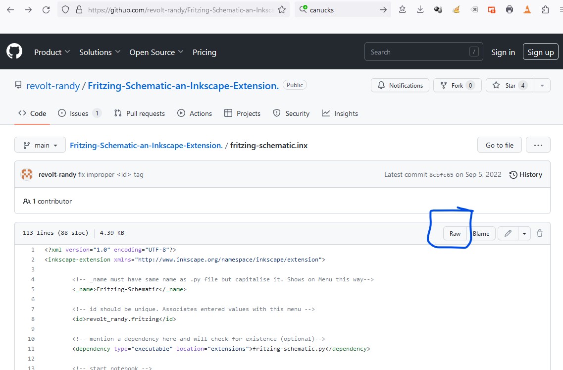
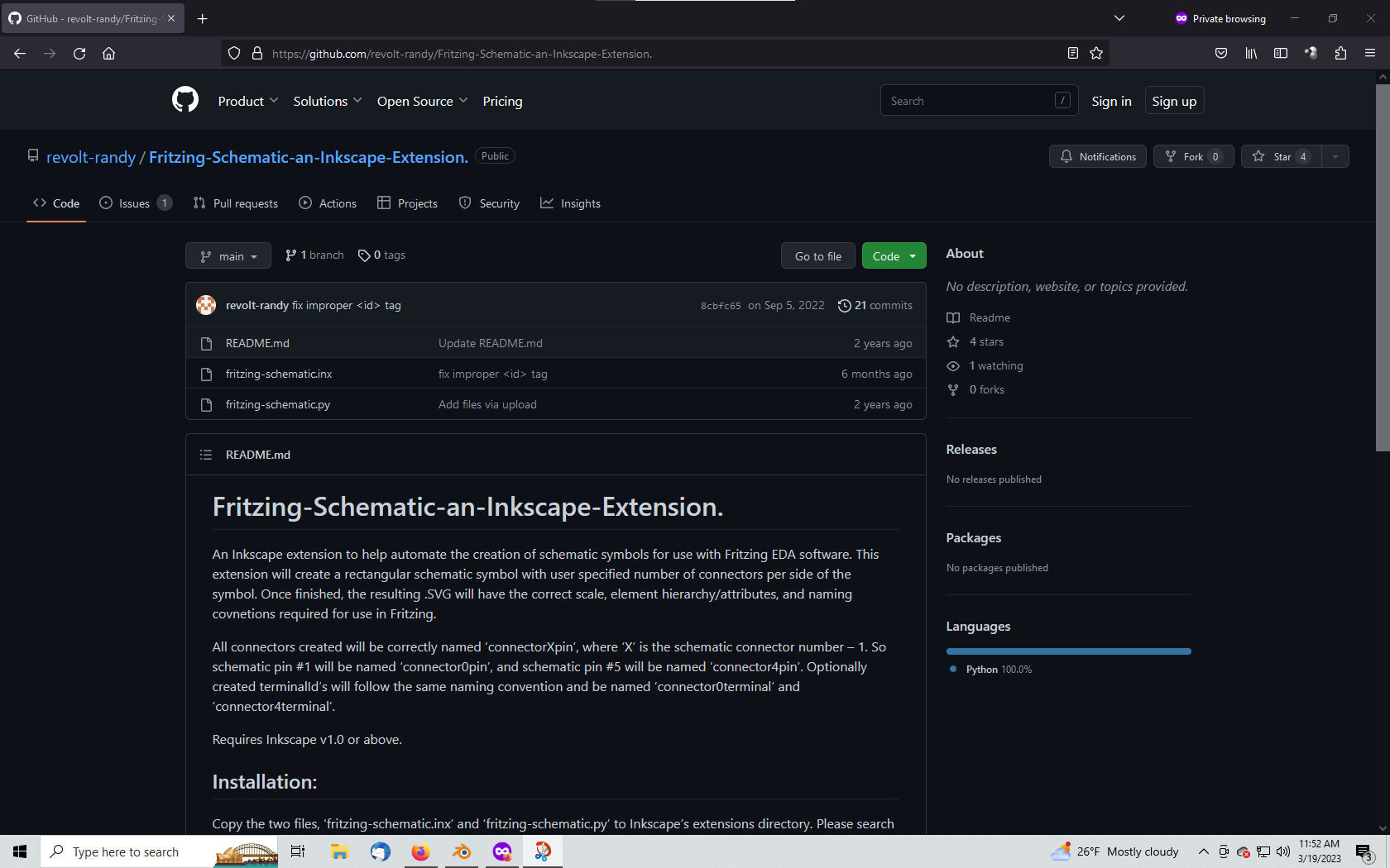
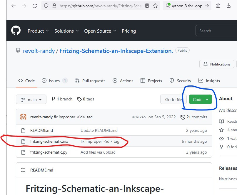
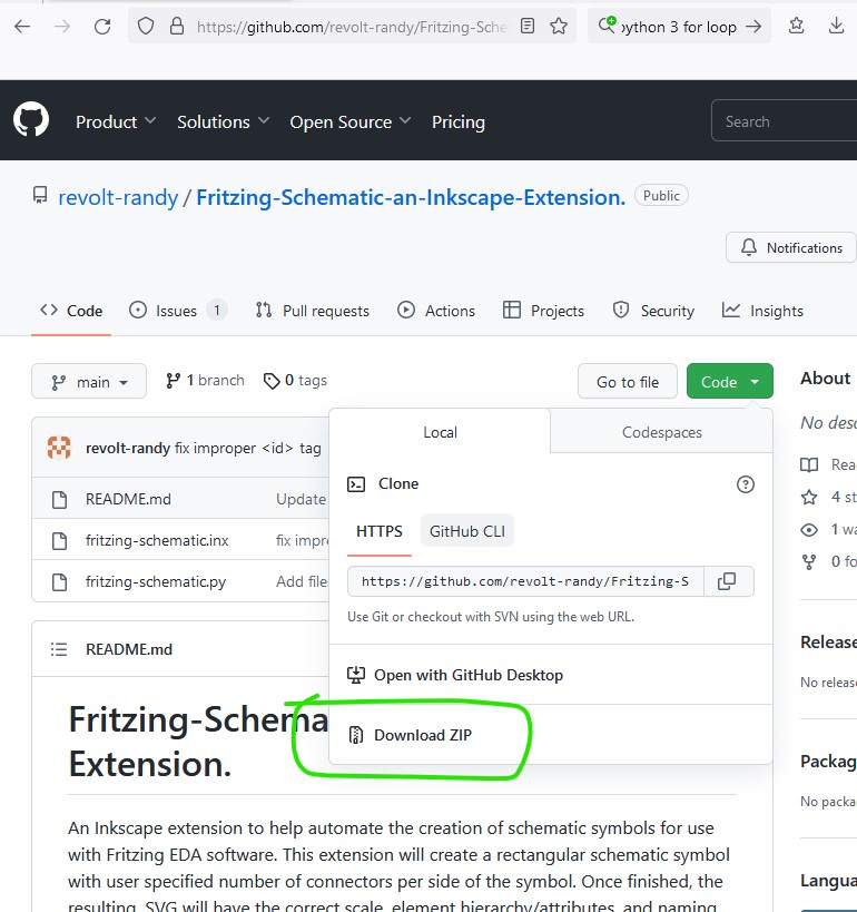
It’s available on github:
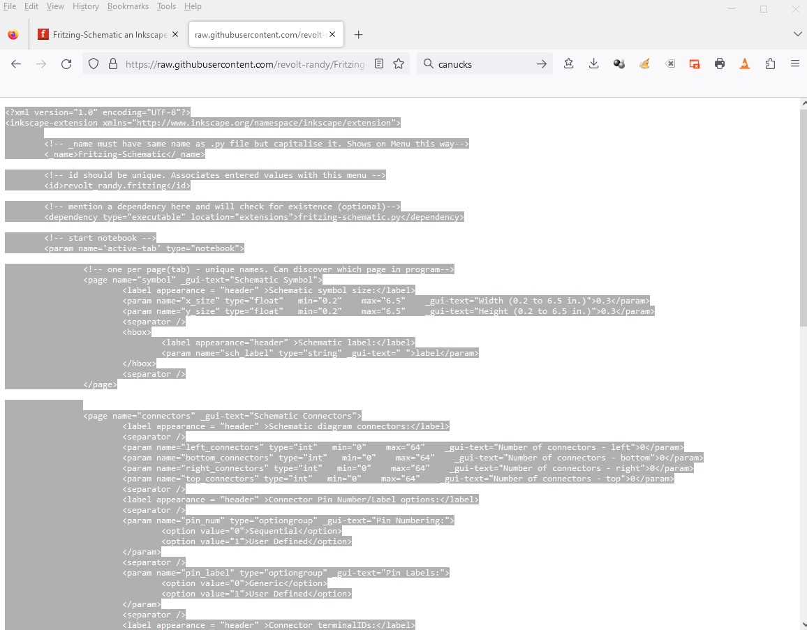
https://github.com/revolt-randy/Fritzing-Schematic-an-Inkscape-Extension.
To install:
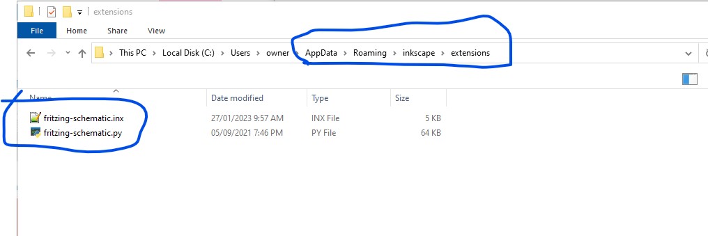
In Inkscape, the edit menu → user preferences → system will have an option for ‘User extensions’ - allowing you to open the folder to store user extensions in for Inkscape. Simply copy fritzing-schematic.inx and fritzing-schematic.py to this directory.
To use:
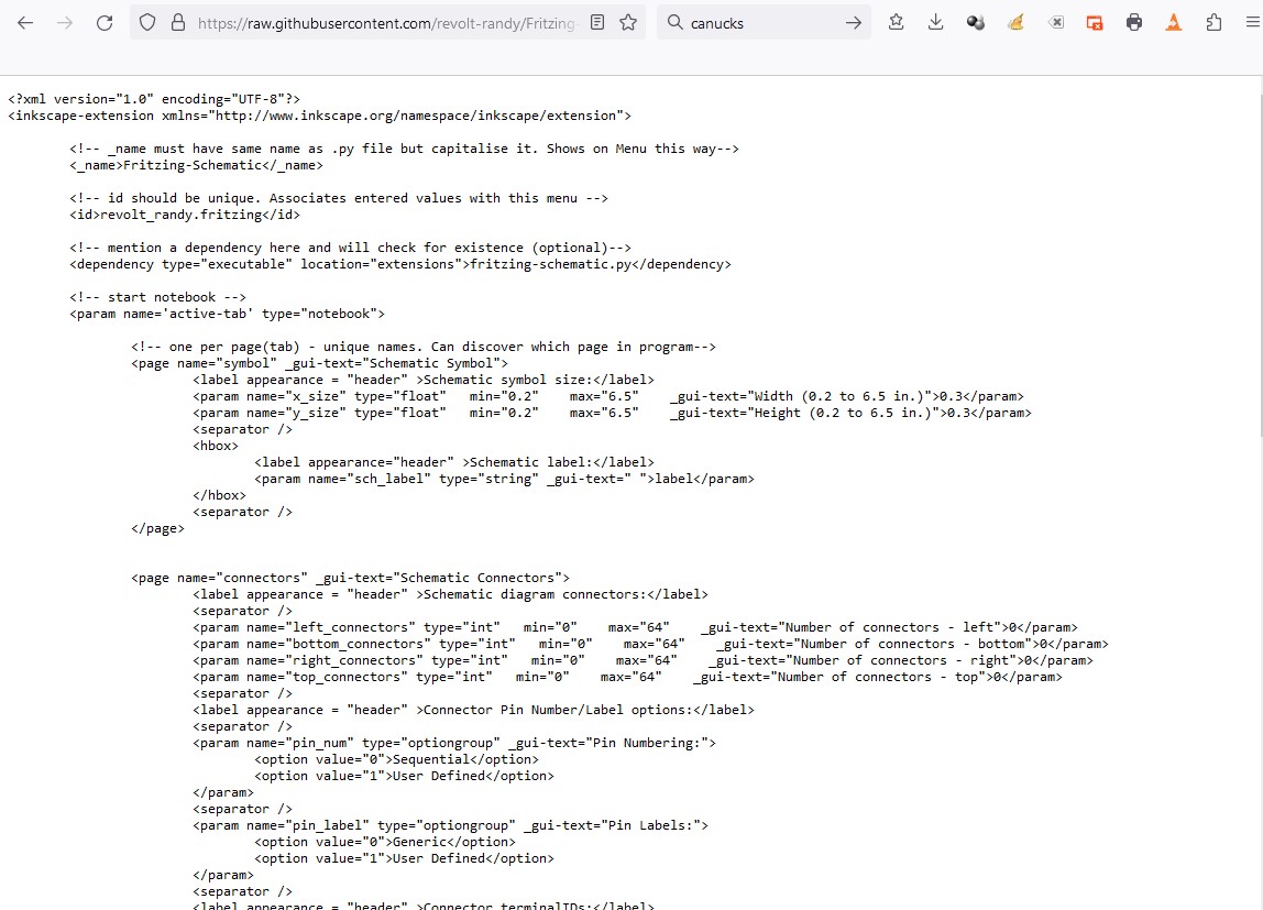
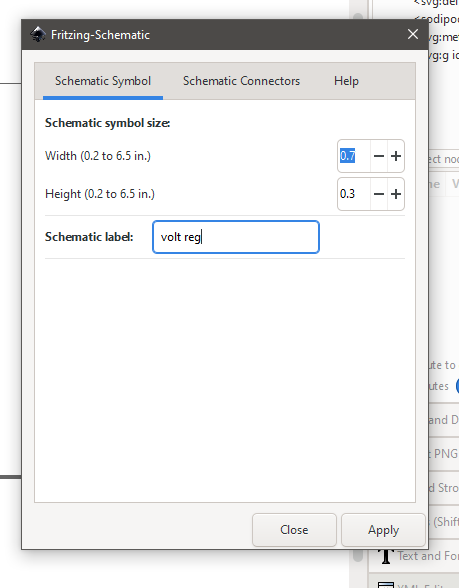
Start the extension via Inkscape’s Extensions menu option under → Fritzing → Fritzing_Schematic… option. This will open a new window in Inkscape for user input with 2 tabs.
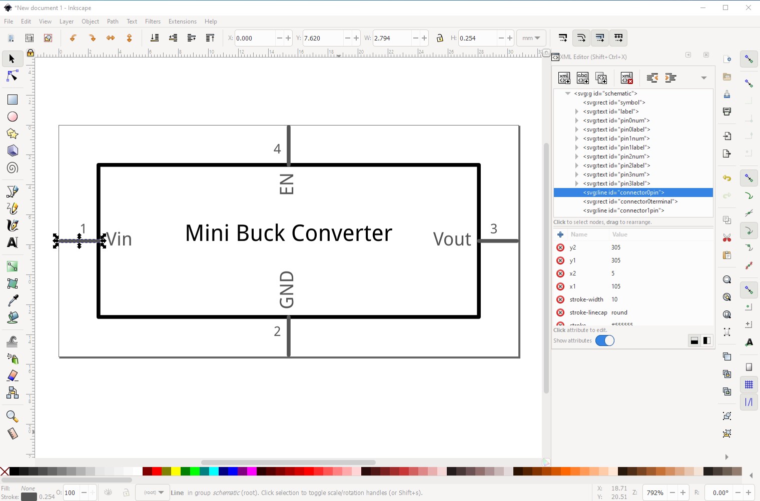
The Schematic Symbol tab is for defining the size of the symbol and the label:
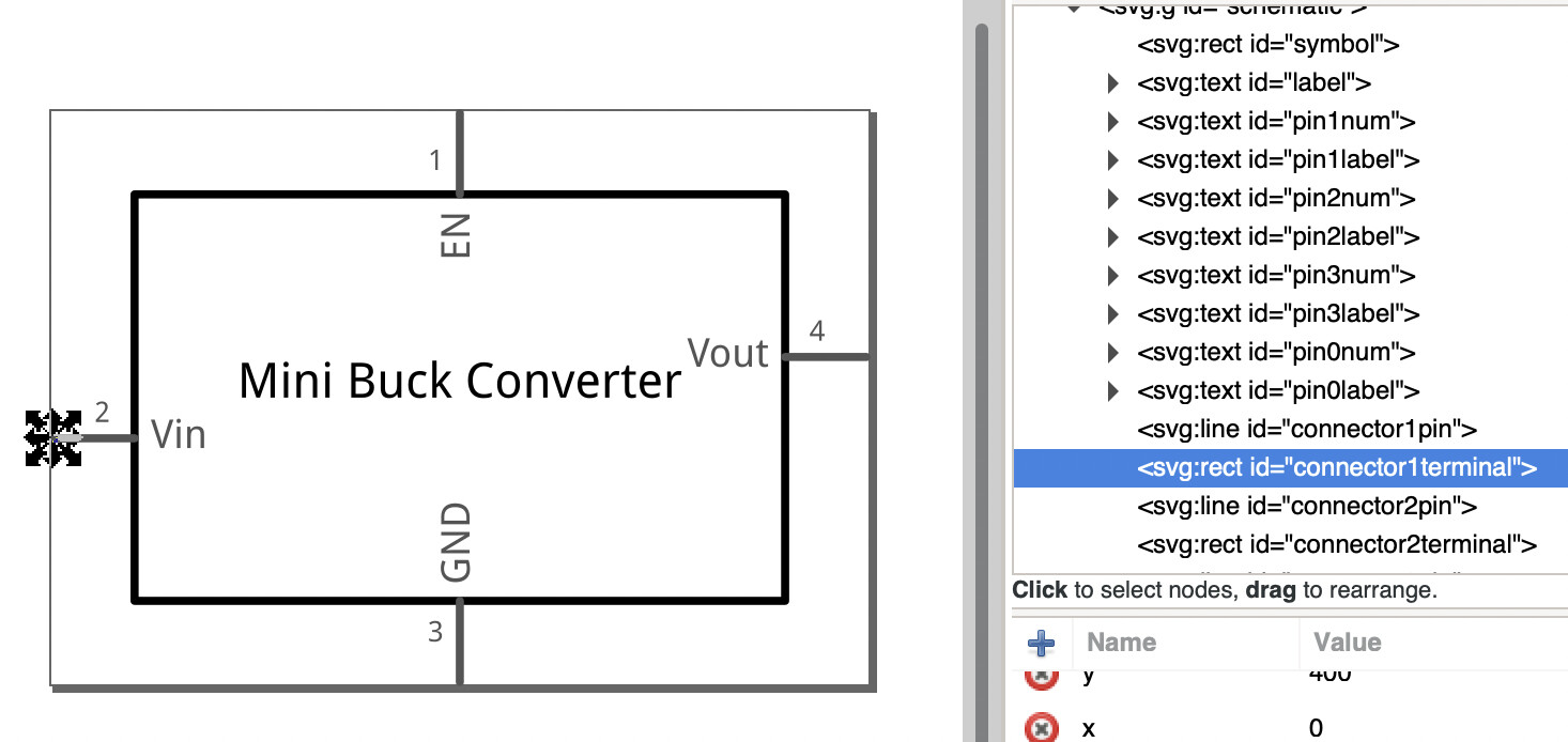
The Schematic Connectors tab is for defining the number of connectors per side of the symbol, pin number/label options and terminalId creation.
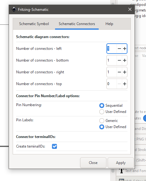
Once the settings have been entered, clicking the ‘Apply’ button starts the extension.
If any User Defined option is checked, additional windows will pop open for user input. Once the data is entered, the schematic symbol will be generated.
Thanks to @vanepp for testing a giving feedback during development
Please post questions/problems/feedback here and I will respond.
Randy