Your svg is misconfigured, as is the fzp file. The svg currently looks like this:
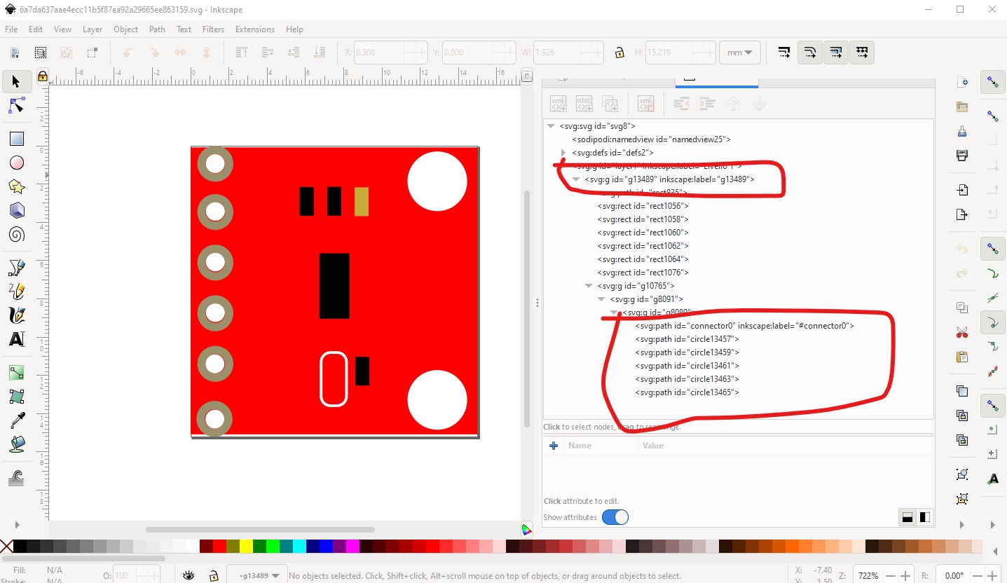
Which is missing the breadboard layerid (the top red circle) and the connector names as set in the fzp file. It should look like this:
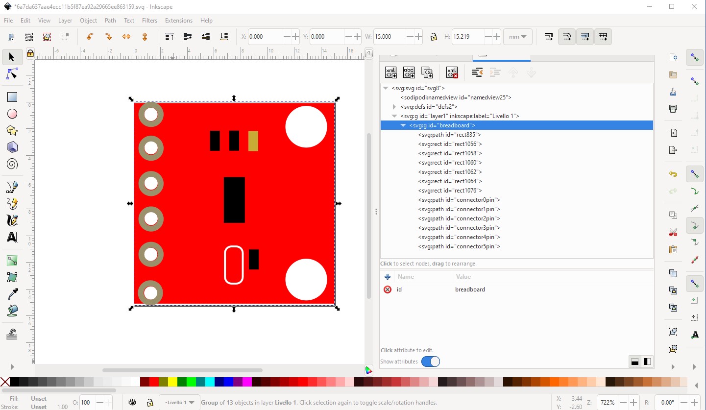
which is this svg

If you unzip the .fzpz file you will find a file called
part.MCP4725_0b209649dd860fe342f521e54cf50b68_2.fzp
which specifies the names of the layerID (breadboard) and pins (connector0pin - connector5pin) that need to be in the svg.
<breadboardView>
 <layers image="breadboard/MCP4725_0b209649dd860fe342f521e54cf50b68_2_breadboard.svg">
  <layer layerId="breadboard"/>
and the required pin names in the svg file in the connectors section (the svgId field in this case):
<connector id="connector0" name="pin1" type="male">
 <description>Vout</description>
 <views>
  <breadboardView>
   <p svgId="connector0pin" terminalId="connector0terminal" layer="breadboard"/>
  </breadboardView>
   </layers>
  </breadboardView>
In this case you don’t need the terminalId and it could be removed from the .fzp file, but will be ignored if it isn’t in the svg. As well you need to change the family from Generic IC to something else as Generic IC will replace your part with a Generic IC if you change a field in Inspector. Changing the family to MCP4725 is what I would do here.
 <properties>
  <property name="family">Generic IC</property>
  <property name="variant">variant 47</property>
to
 <properties>
  <property name="family">MCP4725</property>
  <property name="variant">variant 47</property>
This can be done in Parts Editor in the meta data section as well. These tutorials (which applies to the current version of Fritzing) may help as well
edit:
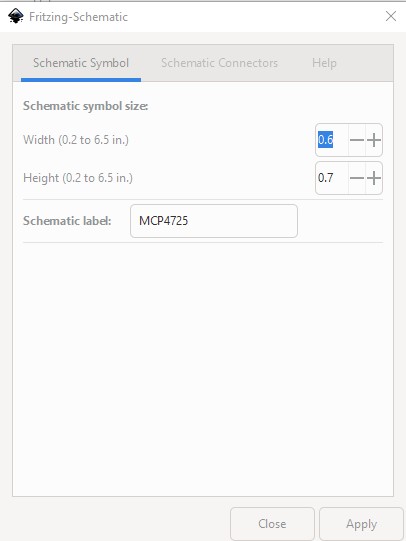
In addition both schematic and pcb are incorrect. Schematic I replaced via this Inkscape extension:
using these paramaters

pcb is a copy of breadboard modified to the requirements of pcb. Note the mounting holes are not drilled, if you want mounting holes you need to drag a hole part from pcb in core parts in to the sketch. Pin names are the same as your .fzp file (and don’t match any breakout board I see!) All these changes are in this part
MCP4725-fixed.fzpz (4.4 KB)
Peter