Someone requested for a part here
So while I was making the part, I decided to record down what I did.
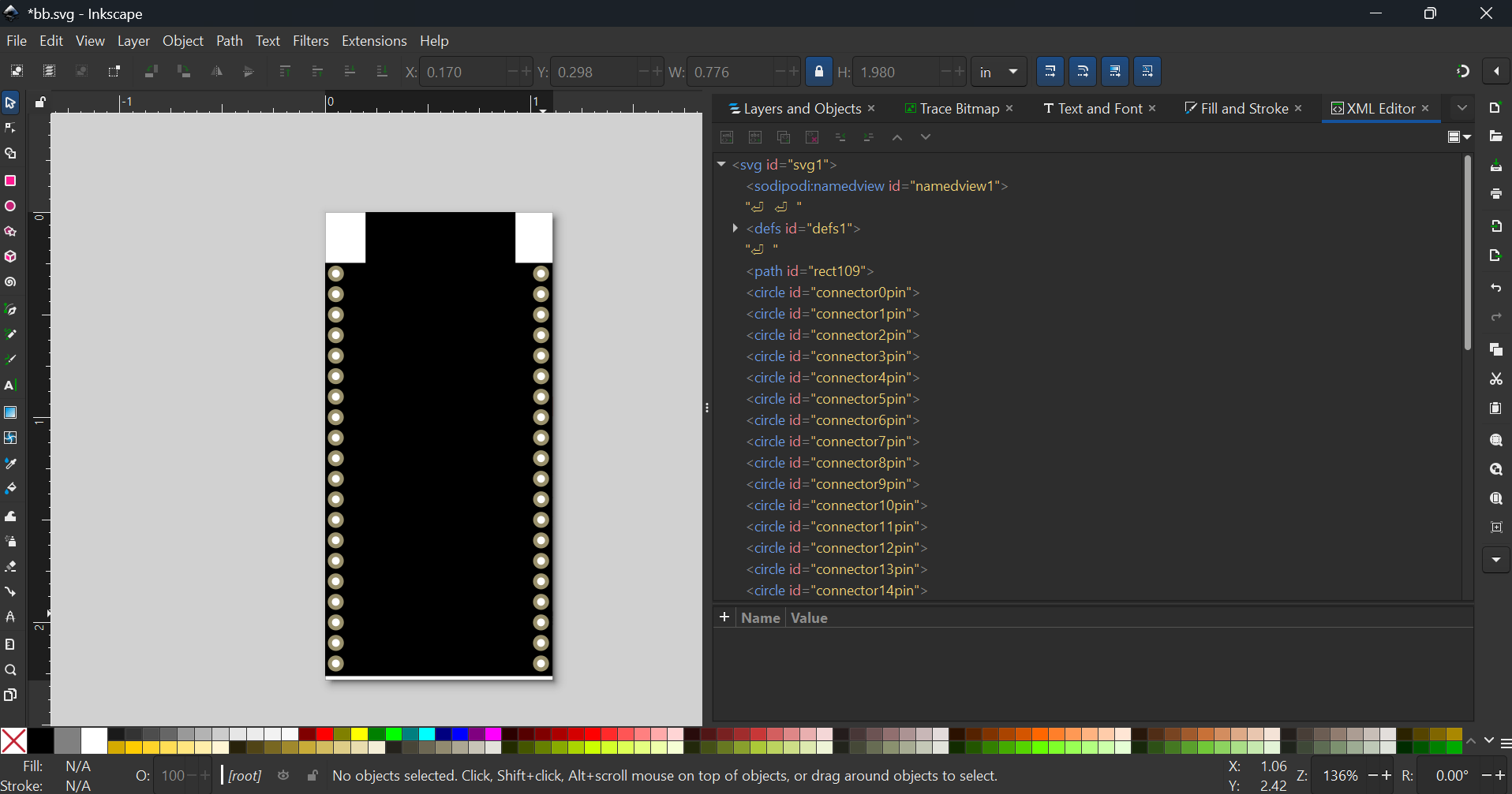
Download these (if you have not done so)
- The Schematic Extension for Inkscape
First download this image
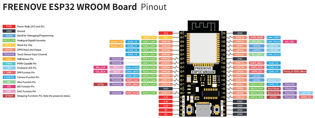
and upload it into Inkscape
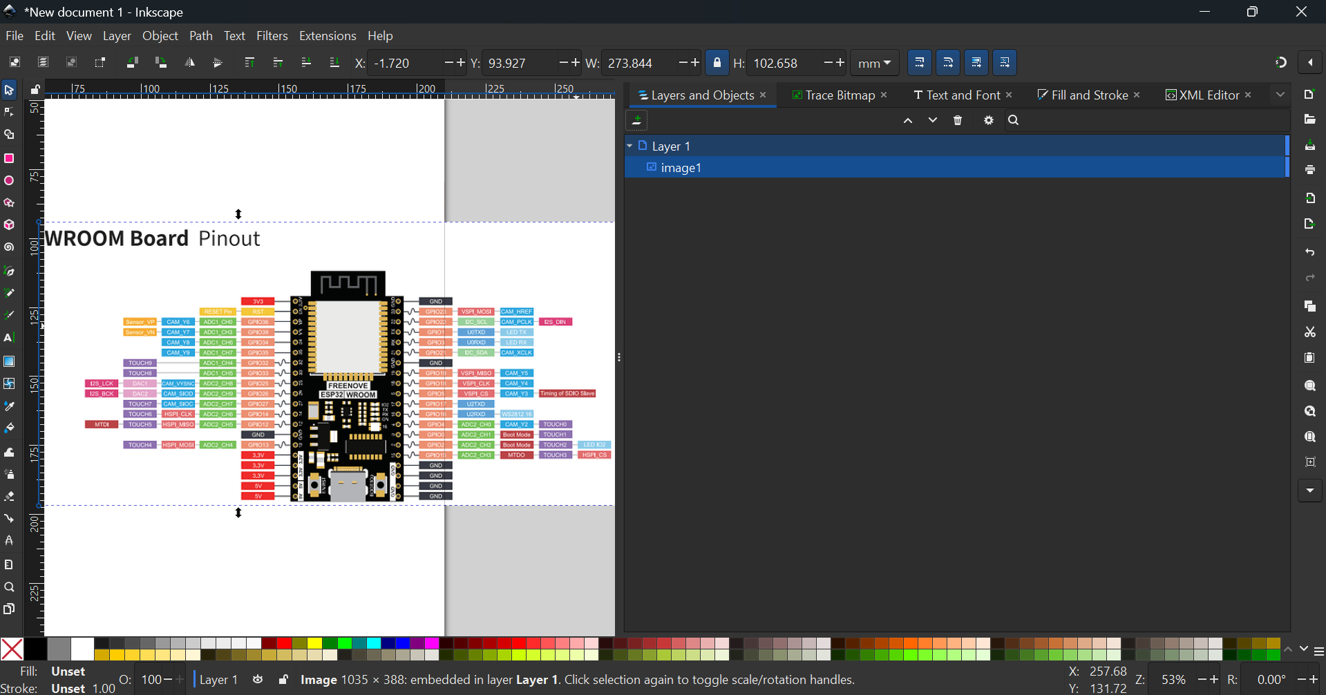
Next, download this SVG of connectors
![]()
Line it on the image
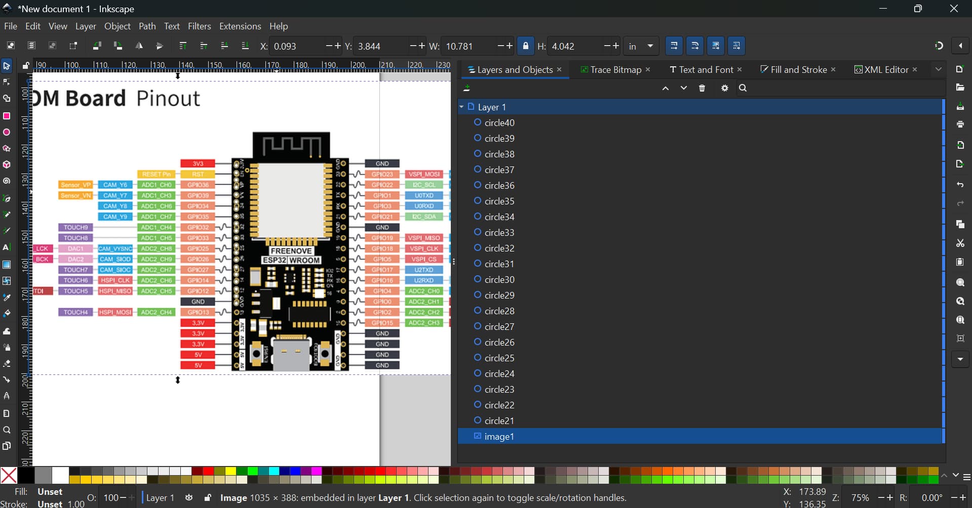
and rescale the image (SVG image below with PNG at the back. As the forum cannot properly render, please download this file and remove the .fzp extension)

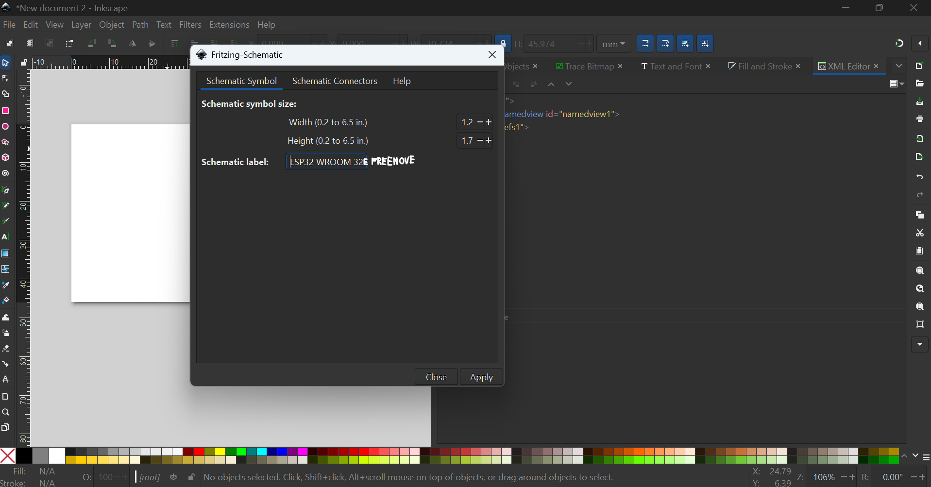
Then, design the part graphic, but first ungroup “Layer1”
This is the most tedious part. and once you’re done you are actually 3/4 done. This tedious process can take up to 2h+, so good luck ![]() You will get this SVG (I let copy paste do the work)
You will get this SVG (I let copy paste do the work)

But, that’s not all.
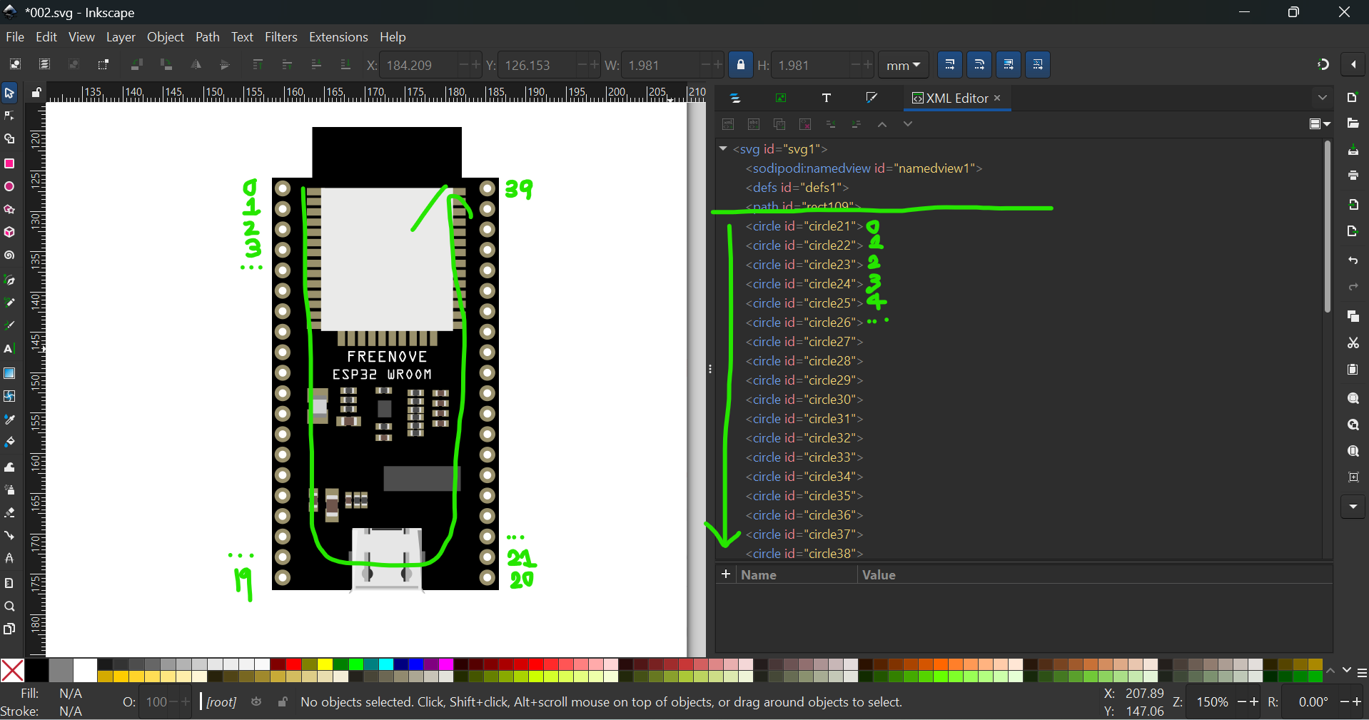
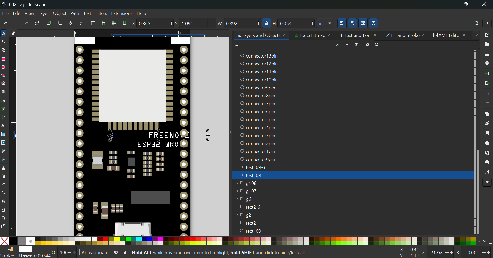
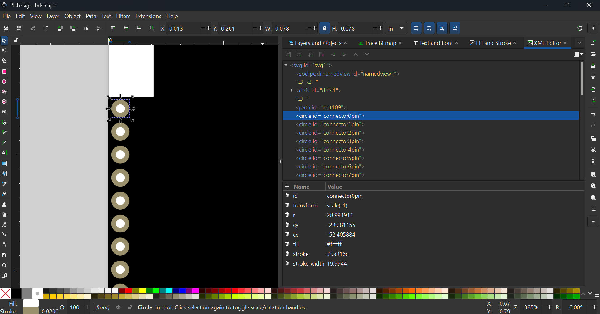
All these elements have to be moved above the connectors (in XML Editor)
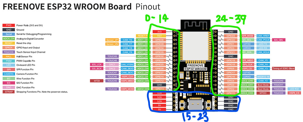
The connectors have to be ordered this way
The easiest way to reorder and rename the pins is to run through E2fRemoveUnusedConnectors.py
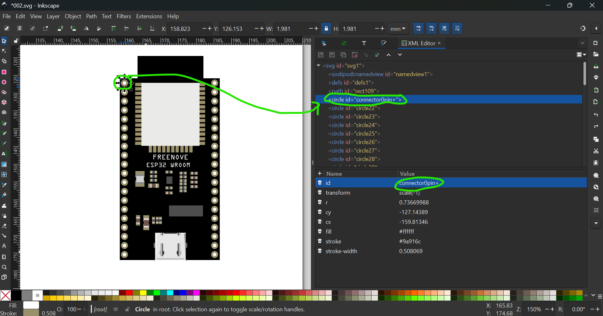
So first rename the first pin to connector0pin+
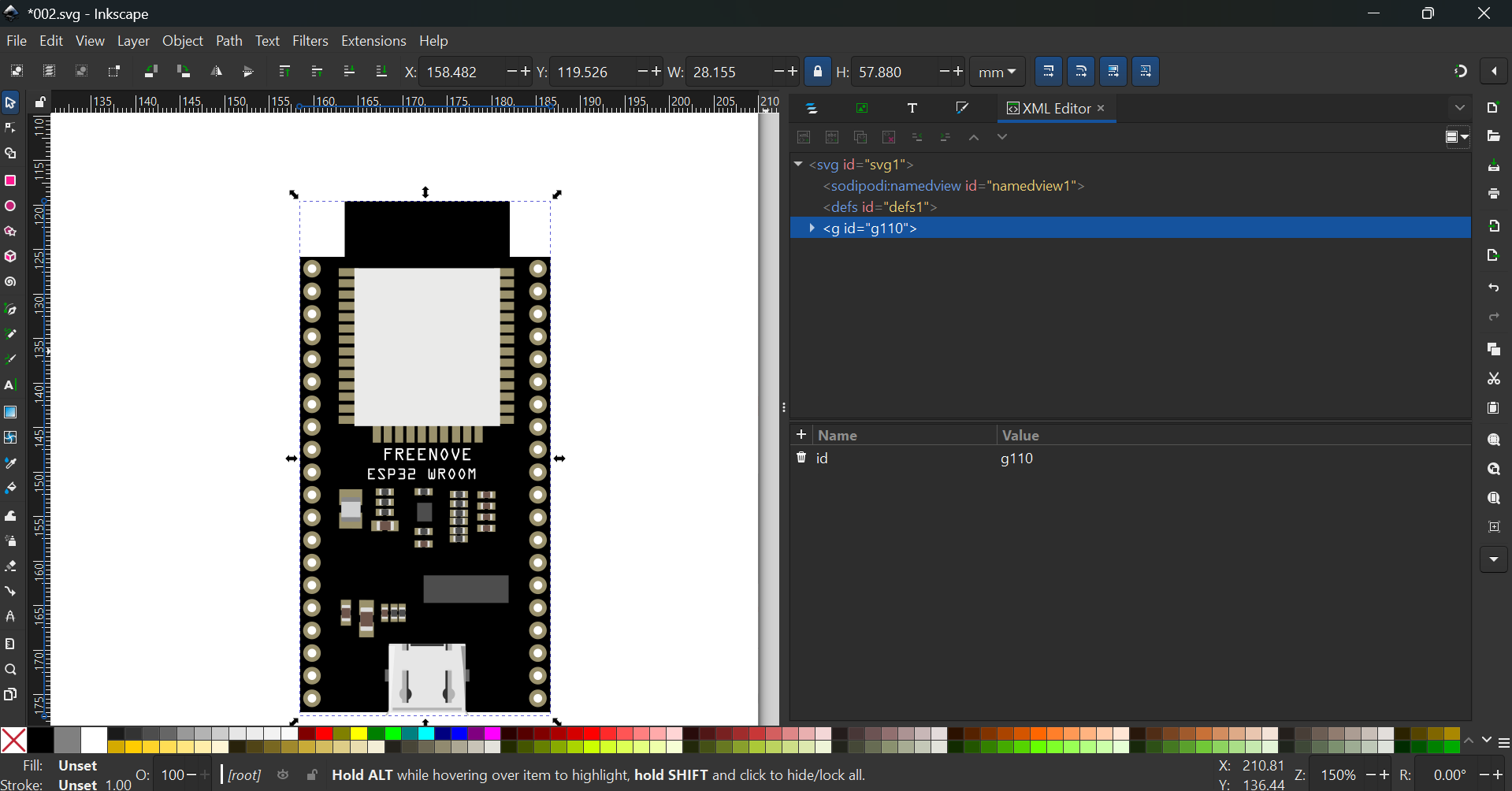
Then, edit → Select All → Ctrl/Cmd + G to group everything
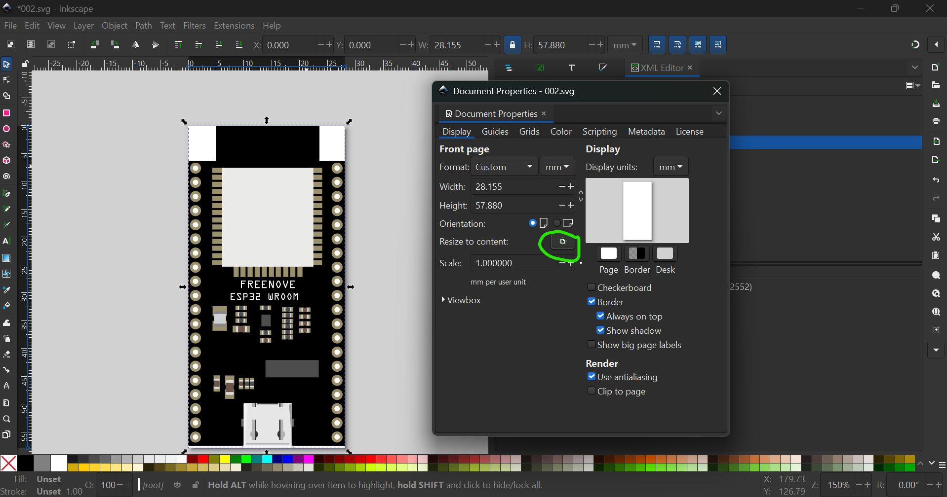
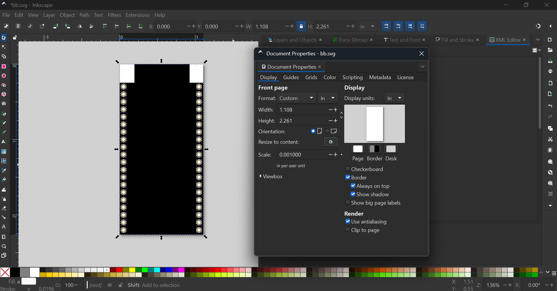
Go to File → Document Properties → Resize Page
Then change all units to in and change scale to 0.001

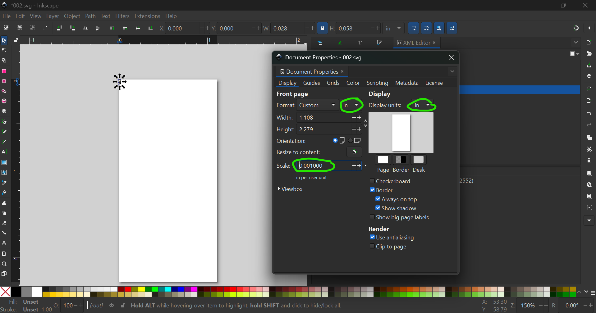
With width and height locked, change the width to its original
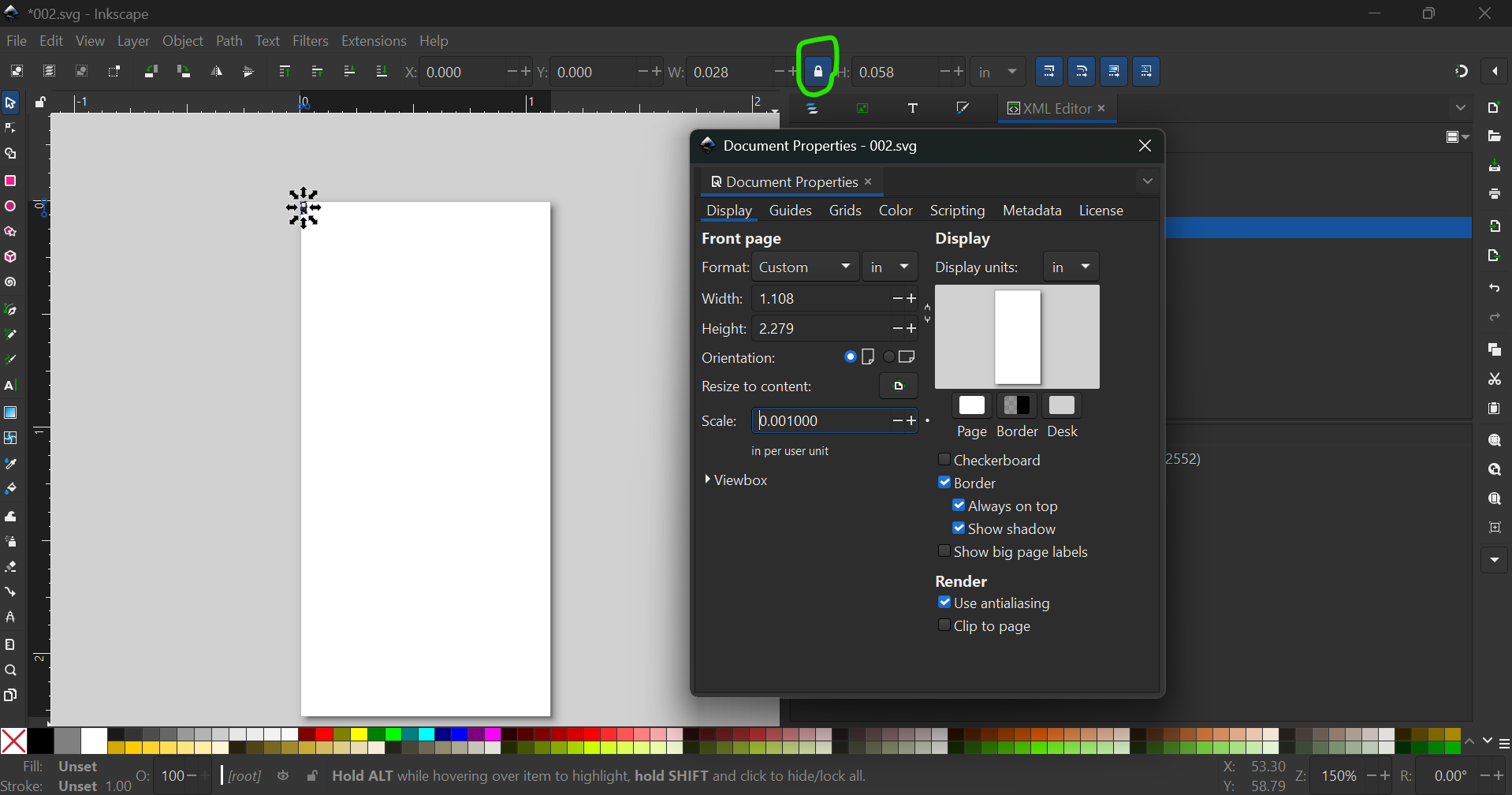
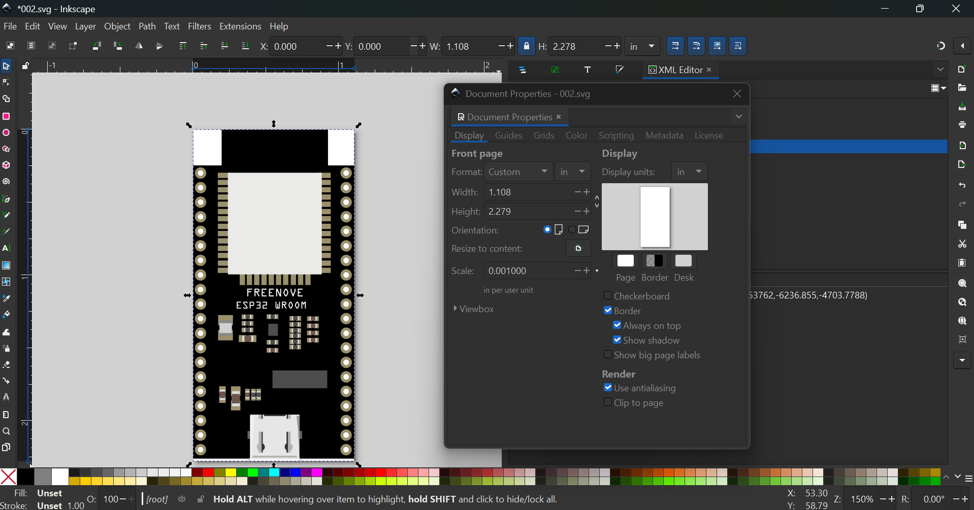
Close the document properties window. Next, ungroup and regroup to remove the transforms, then rename group to breadboard

Now save the svg

and run it with E2fRemoveUnusedConnectors.py
Docs:
Warning
The python scripts can be fairly rough. They may need to be modified to do what you want
OUTPUT
***    Process 002.svg    ***


line 1537 connector 'connector0pin+' changed to 'connector0pin'.

line 1545 connector 'circle22' changed to 'connector1pin'.

line 1553 connector 'circle23' changed to 'connector2pin'.

line 1561 connector 'circle24' changed to 'connector3pin'.

line 1569 connector 'circle25' changed to 'connector4pin'.

line 1577 connector 'circle26' changed to 'connector5pin'.

line 1585 connector 'circle27' changed to 'connector6pin'.

line 1593 connector 'circle28' changed to 'connector7pin'.

line 1601 connector 'circle29' changed to 'connector8pin'.

line 1609 connector 'circle30' changed to 'connector9pin'.

line 1617 connector 'circle31' changed to 'connector10pin'.

line 1625 connector 'circle32' changed to 'connector11pin'.

line 1633 connector 'circle33' changed to 'connector12pin'.

line 1641 connector 'circle34' changed to 'connector13pin'.

line 1649 connector 'circle35' changed to 'connector14pin'.

line 1657 connector 'circle36' changed to 'connector15pin'.

line 1665 connector 'circle37' changed to 'connector16pin'.

line 1673 connector 'circle38' changed to 'connector17pin'.

line 1681 connector 'circle39' changed to 'connector18pin'.

line 1689 connector 'circle40' changed to 'connector19pin'.

line 1696 connector 'circle1' changed to 'connector20pin'.

line 1703 connector 'circle2' changed to 'connector21pin'.

line 1710 connector 'circle3' changed to 'connector22pin'.

line 1717 connector 'circle4' changed to 'connector23pin'.

line 1724 connector 'circle5' changed to 'connector24pin'.

line 1731 connector 'circle6' changed to 'connector25pin'.

line 1738 connector 'circle7' changed to 'connector26pin'.

line 1745 connector 'circle8' changed to 'connector27pin'.

line 1752 connector 'circle9' changed to 'connector28pin'.

line 1759 connector 'circle10' changed to 'connector29pin'.

line 1766 connector 'circle11' changed to 'connector30pin'.

line 1773 connector 'circle12' changed to 'connector31pin'.

line 1780 connector 'circle13' changed to 'connector32pin'.

line 1787 connector 'circle14' changed to 'connector33pin'.

line 1794 connector 'circle15' changed to 'connector34pin'.

line 1801 connector 'circle16' changed to 'connector35pin'.

line 1808 connector 'circle17' changed to 'connector36pin'.

line 1815 connector 'circle18' changed to 'connector37pin'.

line 1822 connector 'circle19' changed to 'connector38pin'.

line 1829 connector 'circle20' changed to 'connector39pin'.
Open the SVG with Inkscape and check if everything went well
At times, the text goes wrong when the program removes PX from font sizes. Then, (sadly), we have to convert everything into paths

Now that we are done, we can move on to Schematic
For the schematic, we want to group the connectors like this
So open a new SVG, then
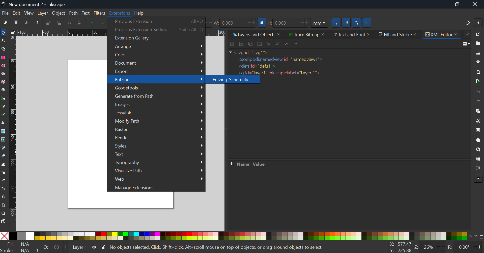

Press Apply, and label the connectors. You will then get this SVG (right-sclick → save as to download this SVG)

Now, go back to the breadboard file, then ungroup
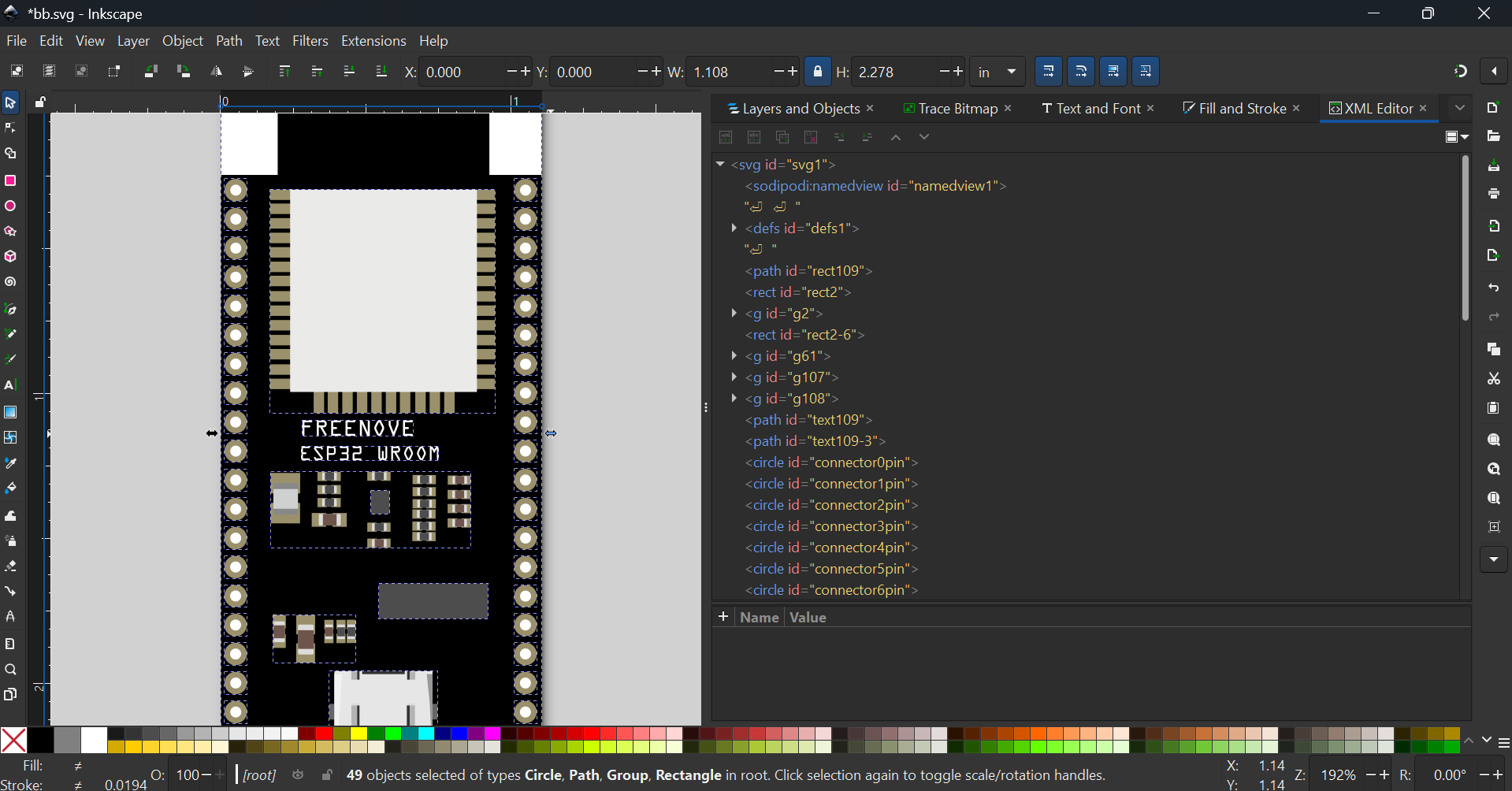
Delete everything except for the connectors
Group everything → file → document properties → resize page to selection → ungroup
Now, select one connector, and change from
to
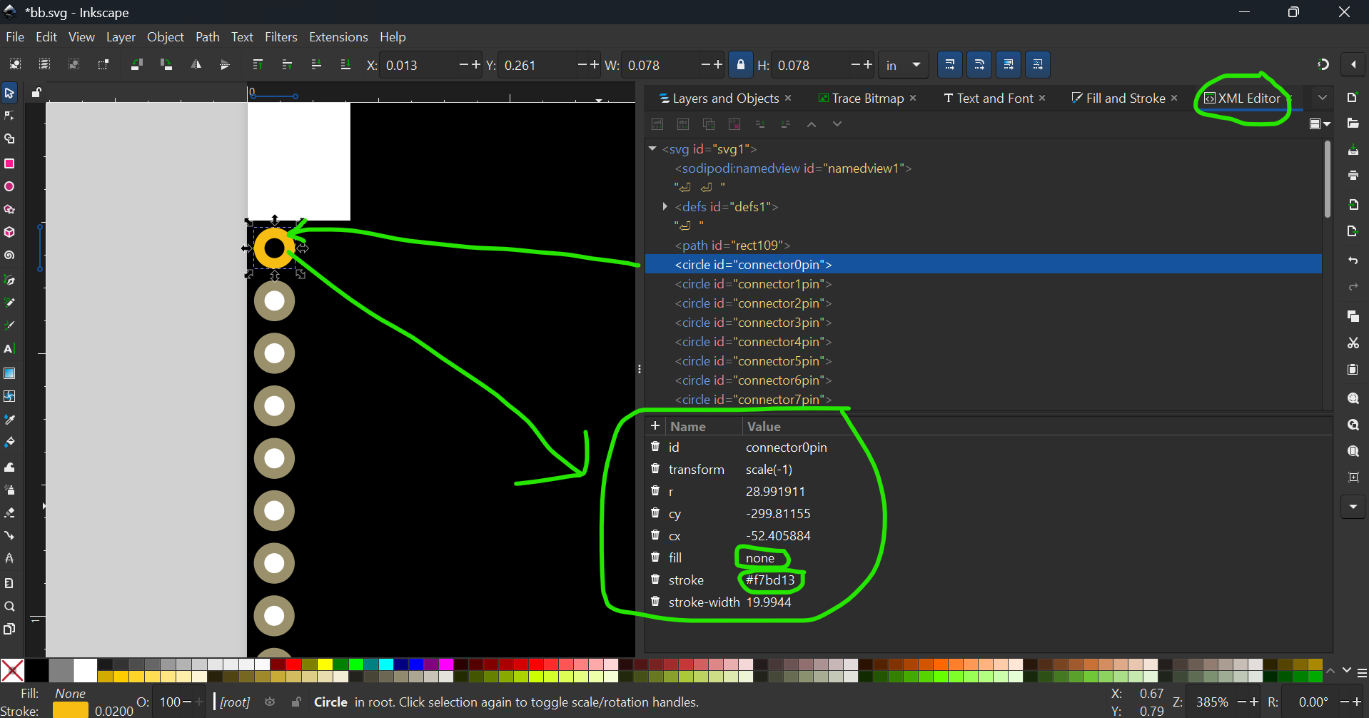
Do same for all other connectors and you’ll get something like this

For the path, change from
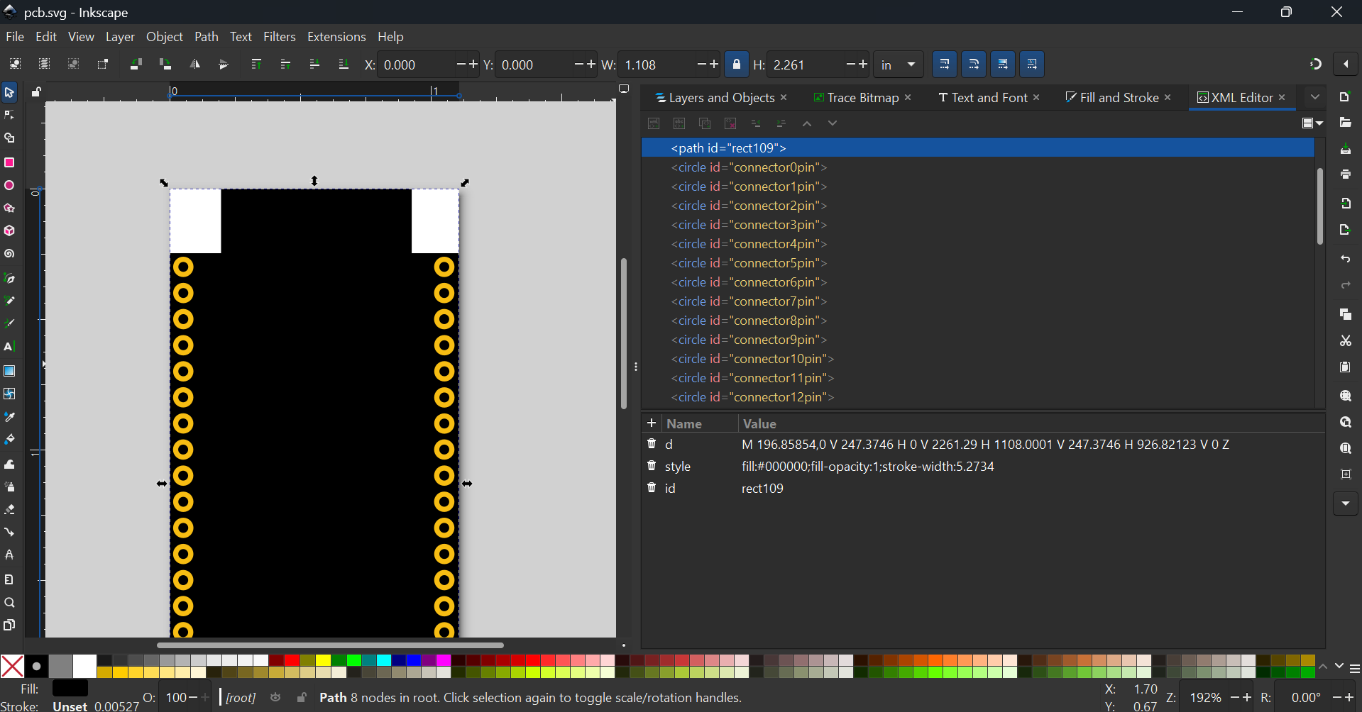
to
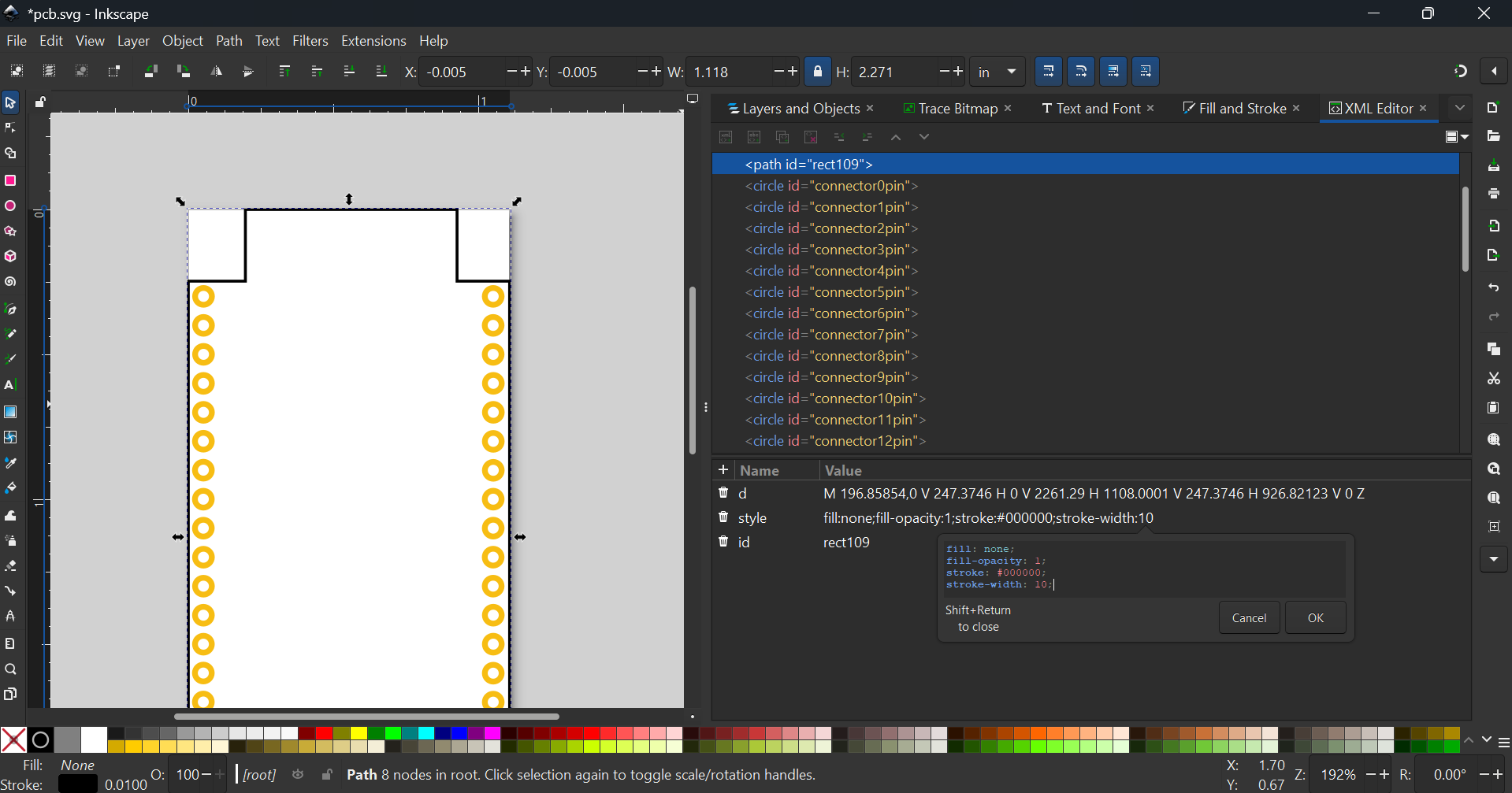
Do second round of viewbox adjustments, then group the path
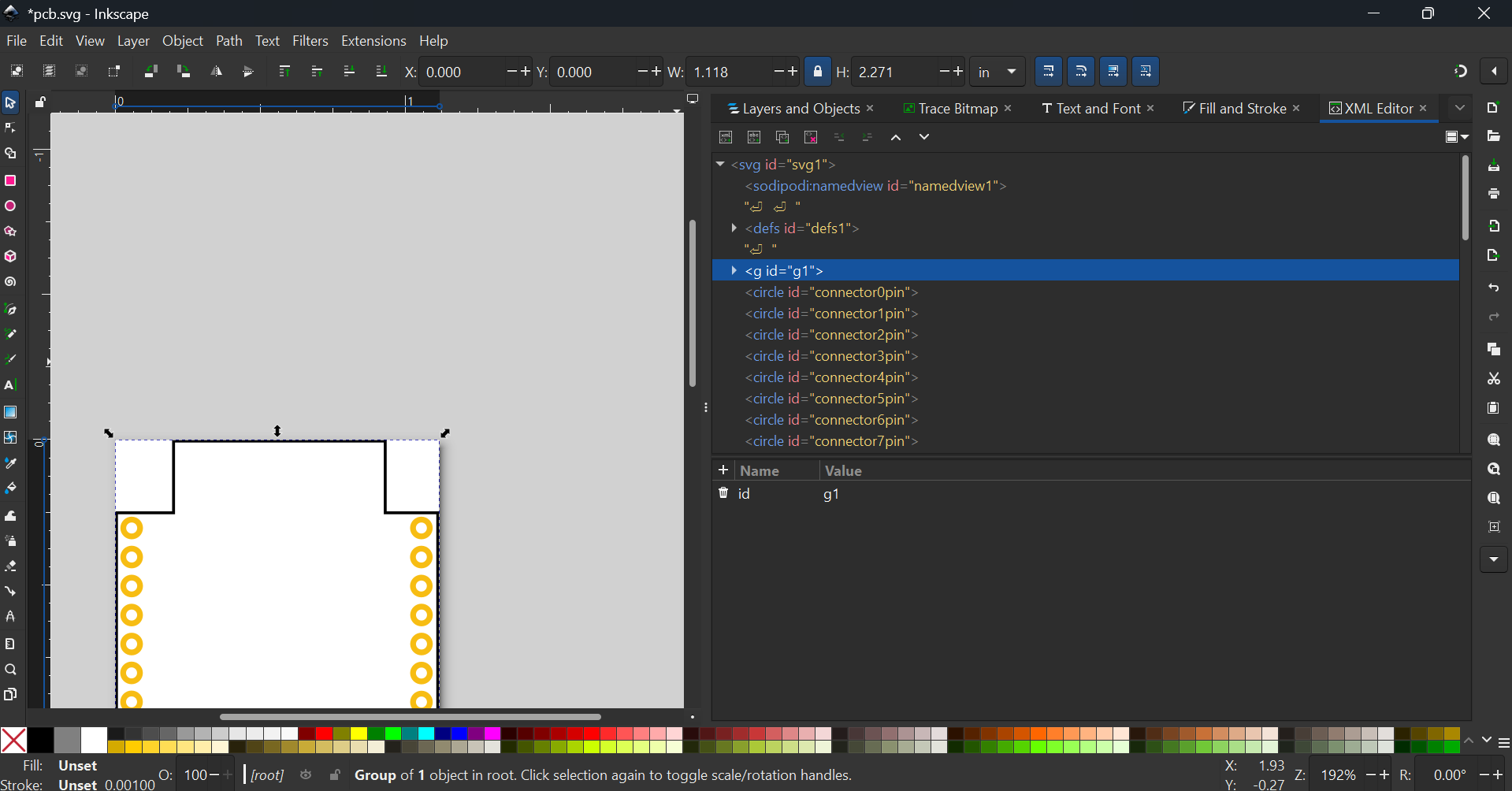
Group the connectors twice
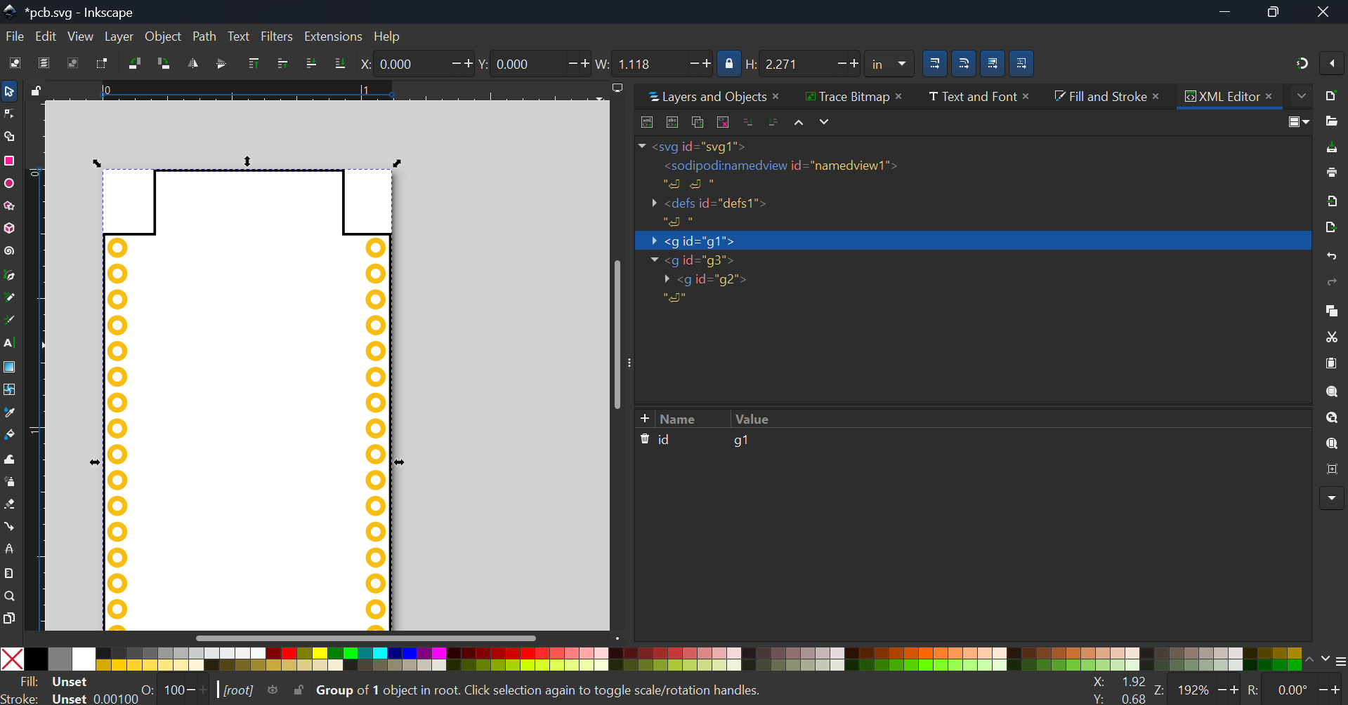
and rename to

(Note: Case sensitive!)
With that we are done with the PCB view

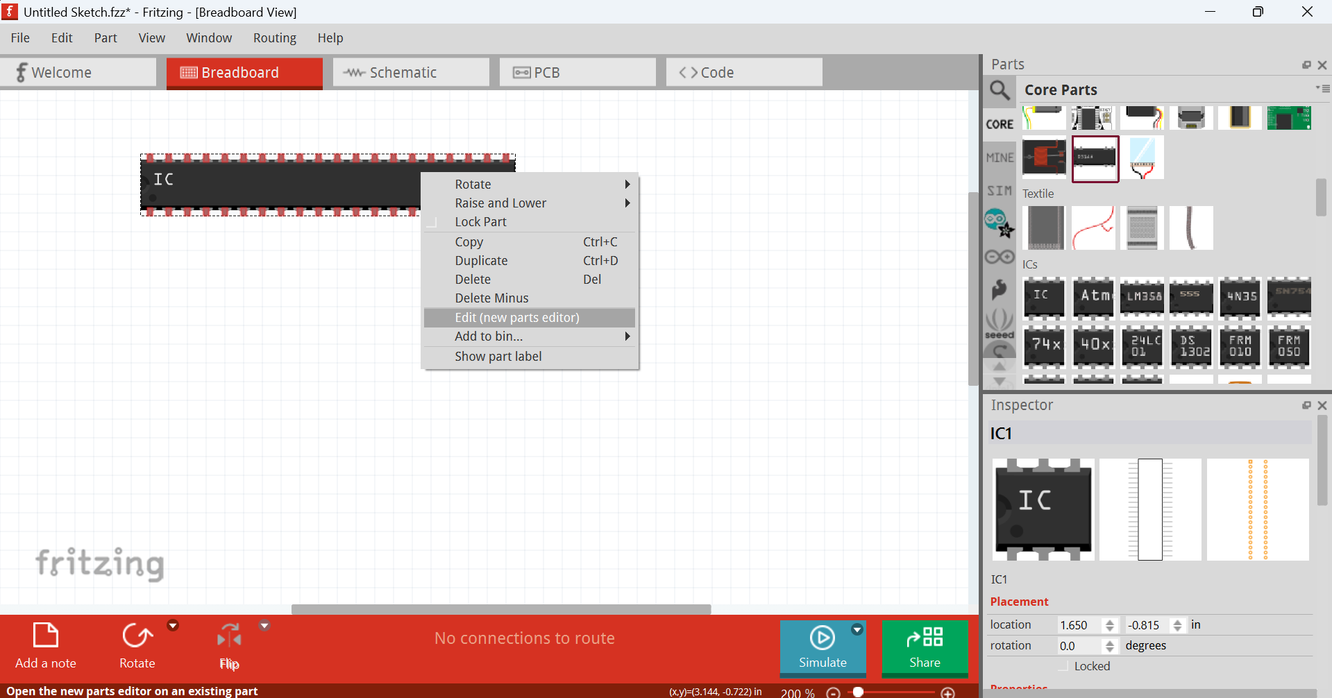
Go to Fritzing and drag out a generic IC, set its no. of pins to 40
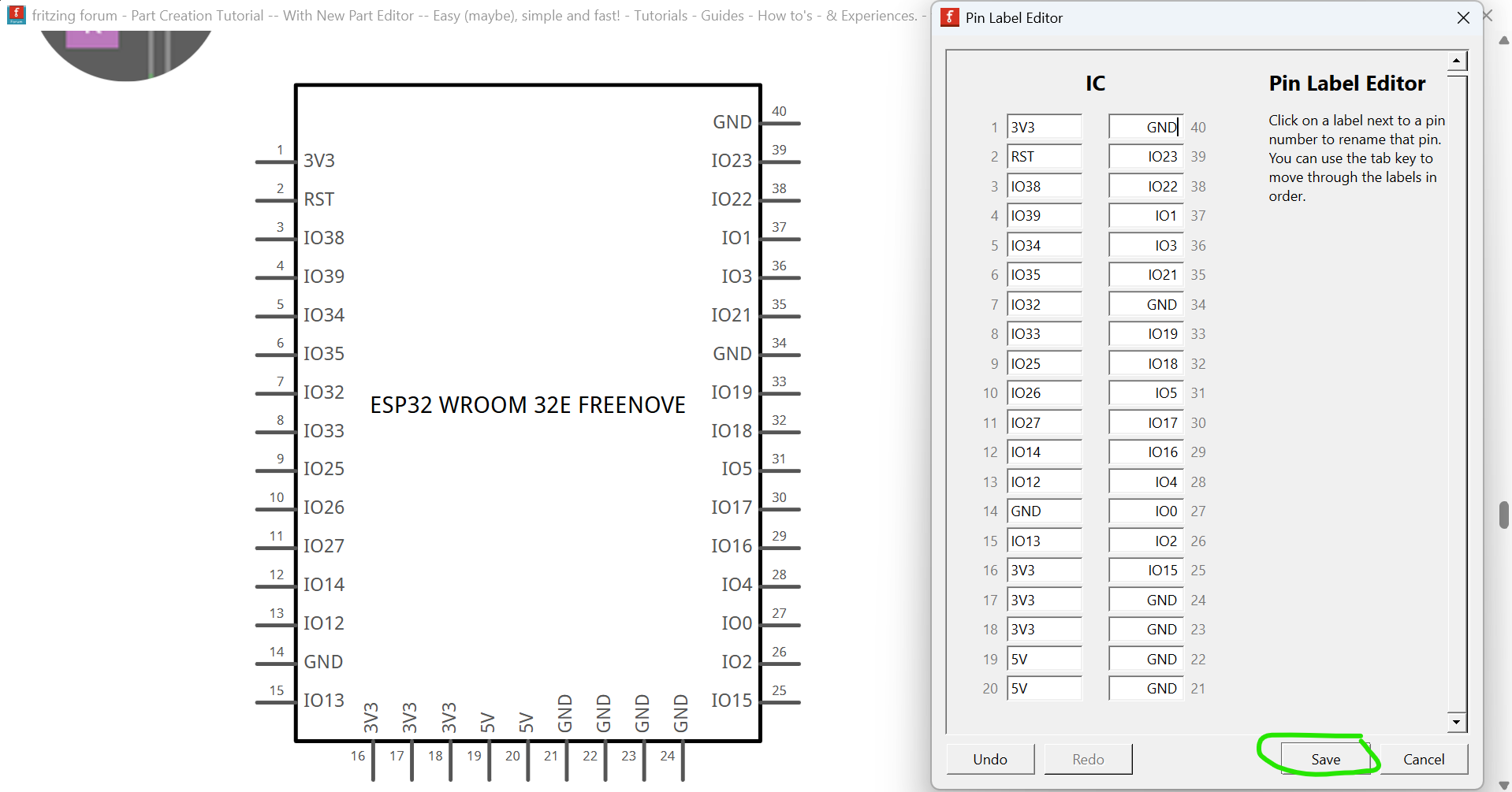
Then, press “Edit Pin Labels”
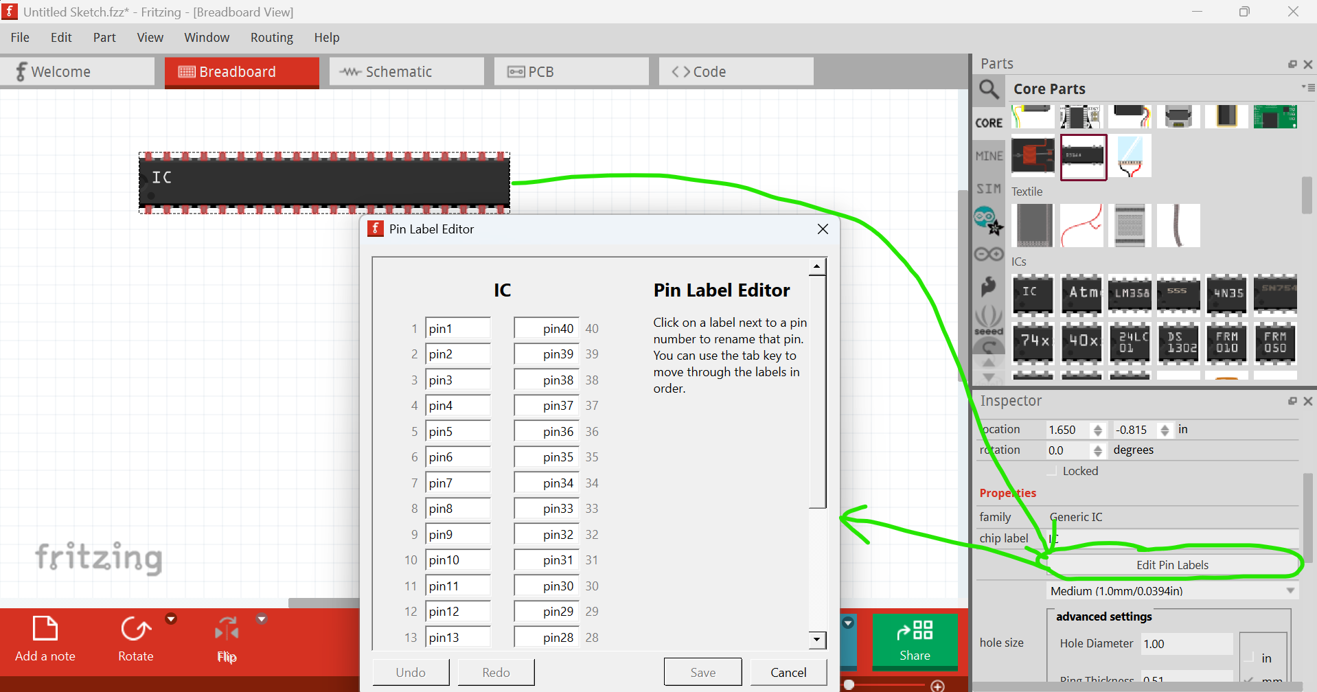
and set the pin labels
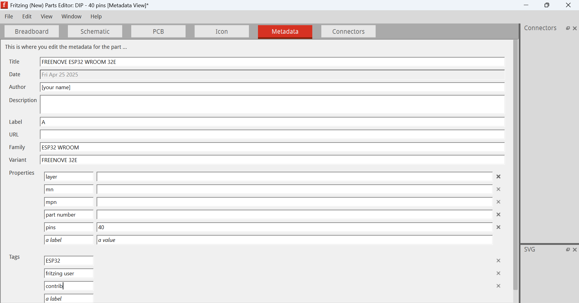
Now, right-click → Edit → Metadata
Change from
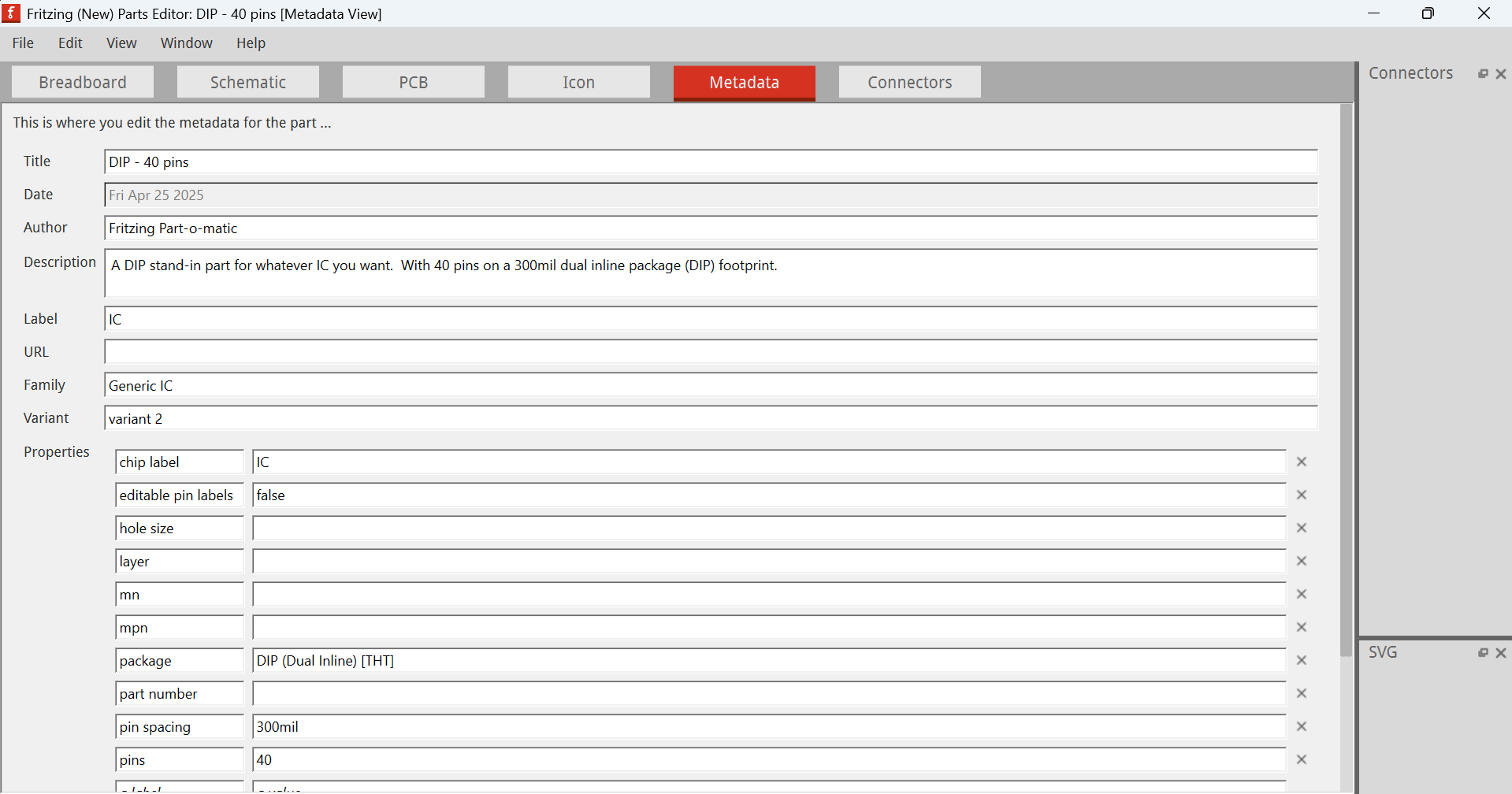
to
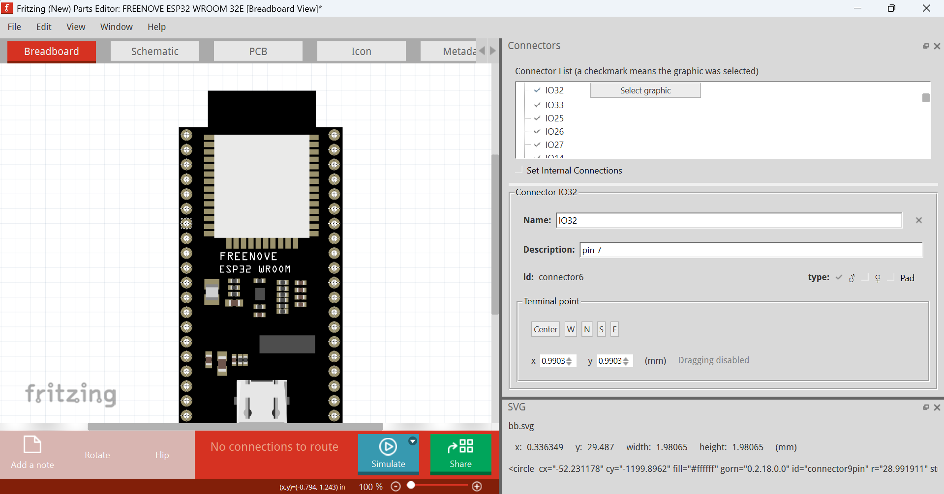
Go to breadboard → file → load image for view → select file → open
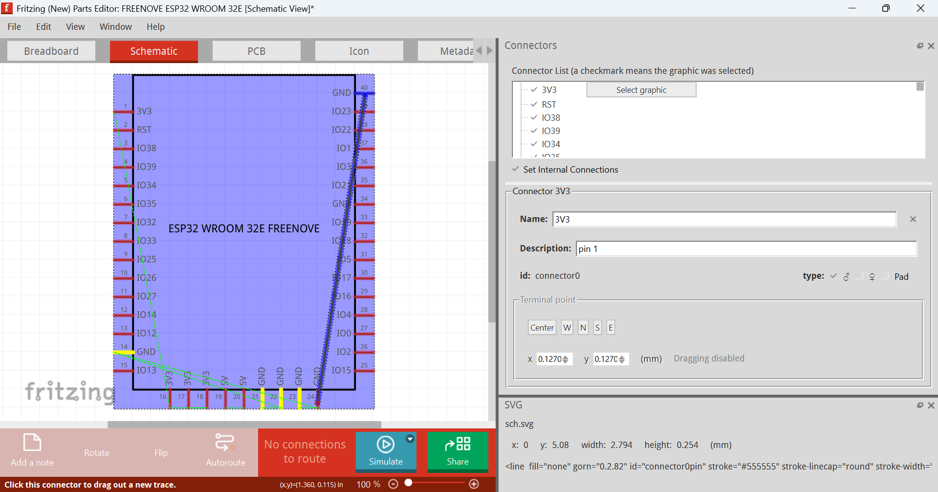
Go to schematic and do the same, but this time, set internal connections (by checking the checkbox
(provided your part which may be another one, has bussed connections)
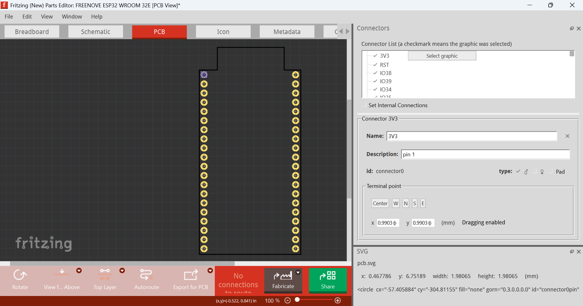
Go to PCB view, and do the same, but don’t set internal connections
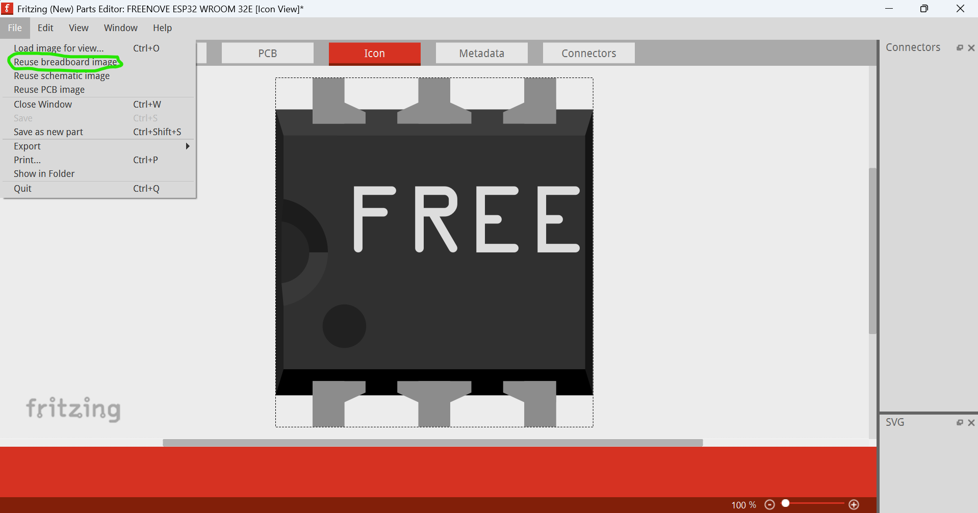
Go to Icon view, then file → reuse breadboard image
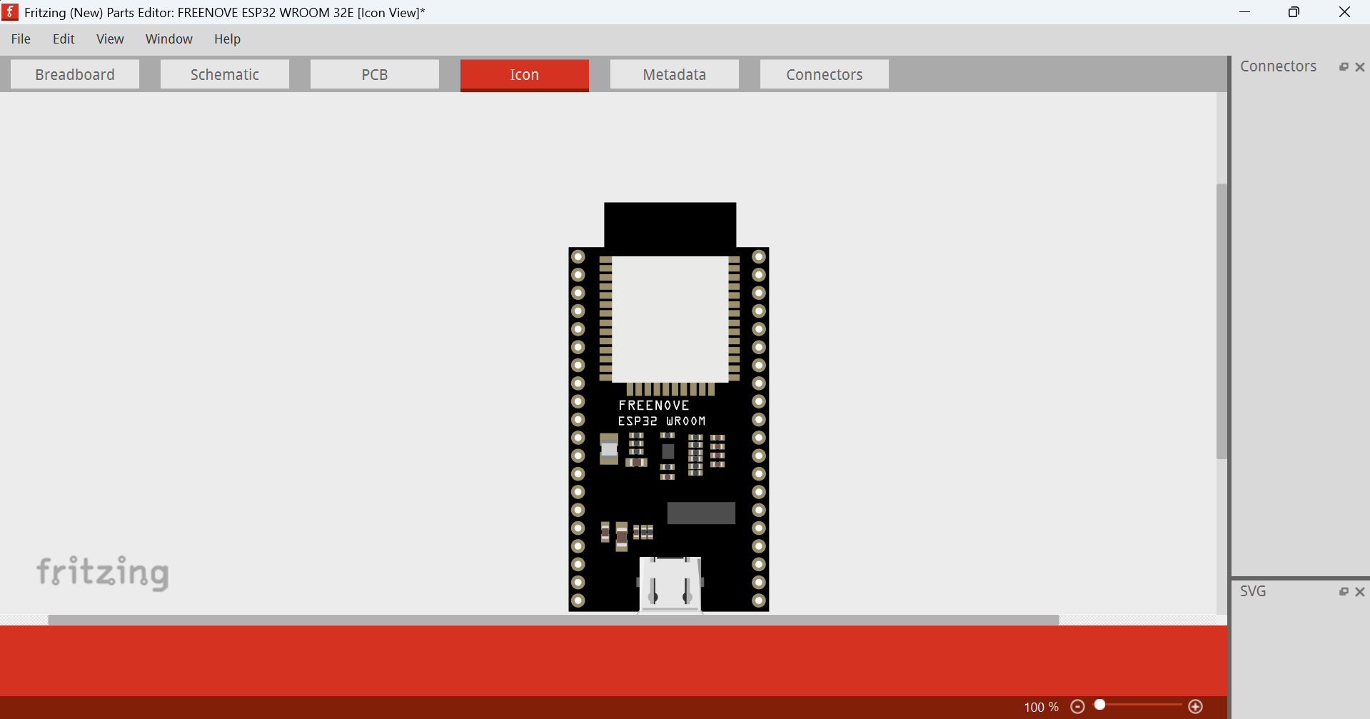
File → Save as new part → ok
That’s all! The part’s done.
When closing Fritzing, be sure to save changes made to the MINE BIN
FREENOVE ESP32 WROOM 32E.fzpz (23.4 KB)