@Jaapio1969 Many problems here
Breadboard
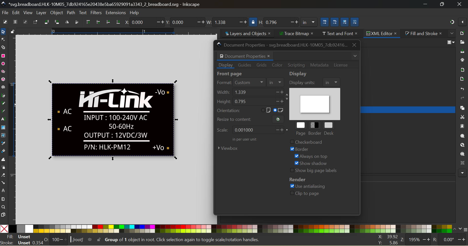
Scale is wrong
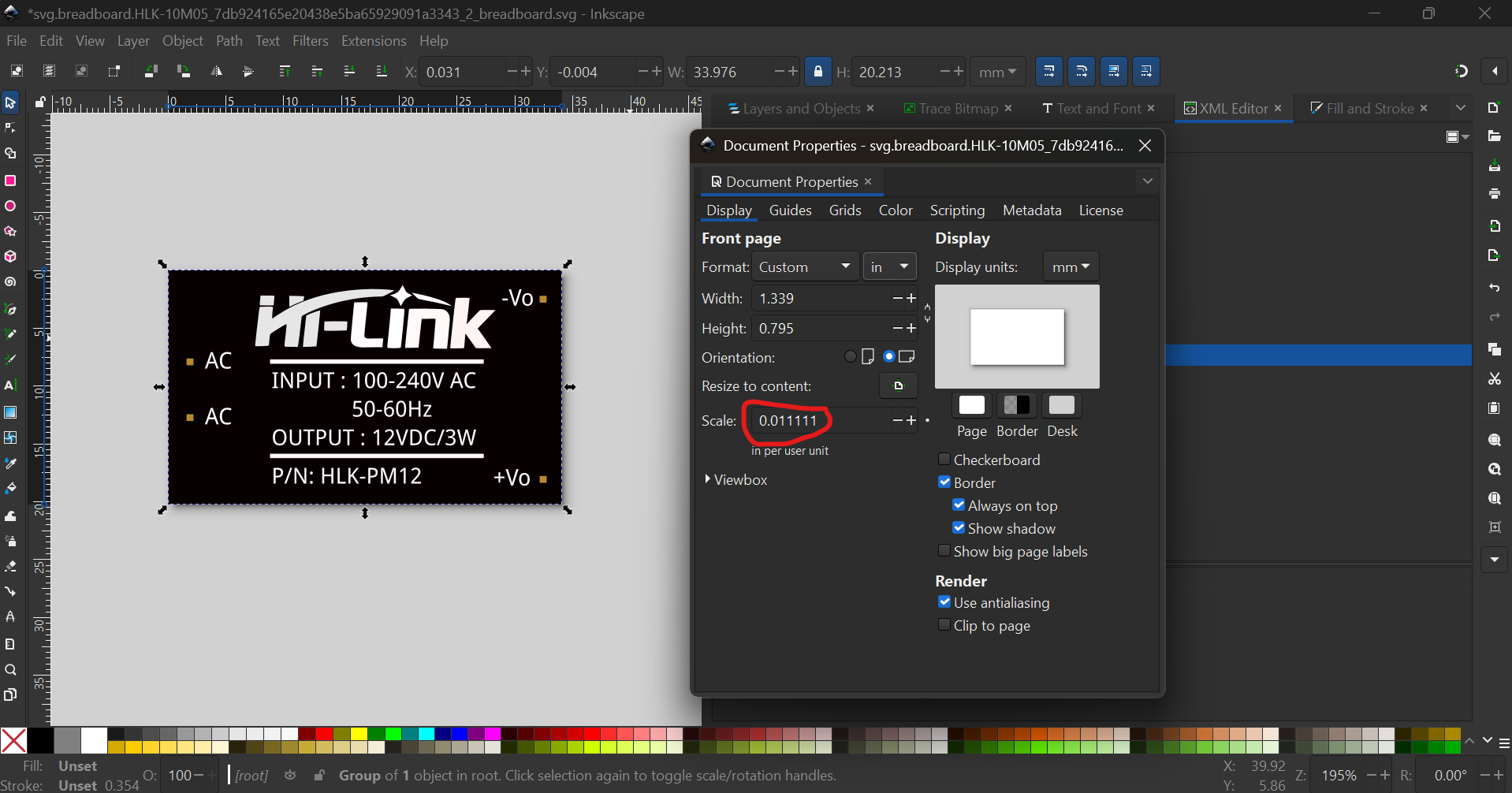
Has to change to

Ungroup everything
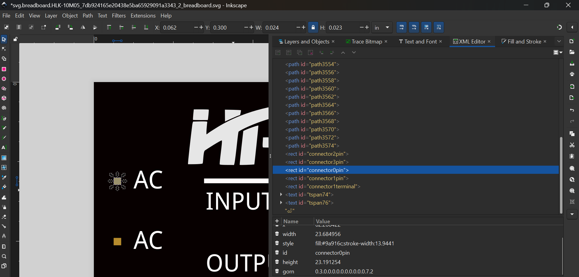
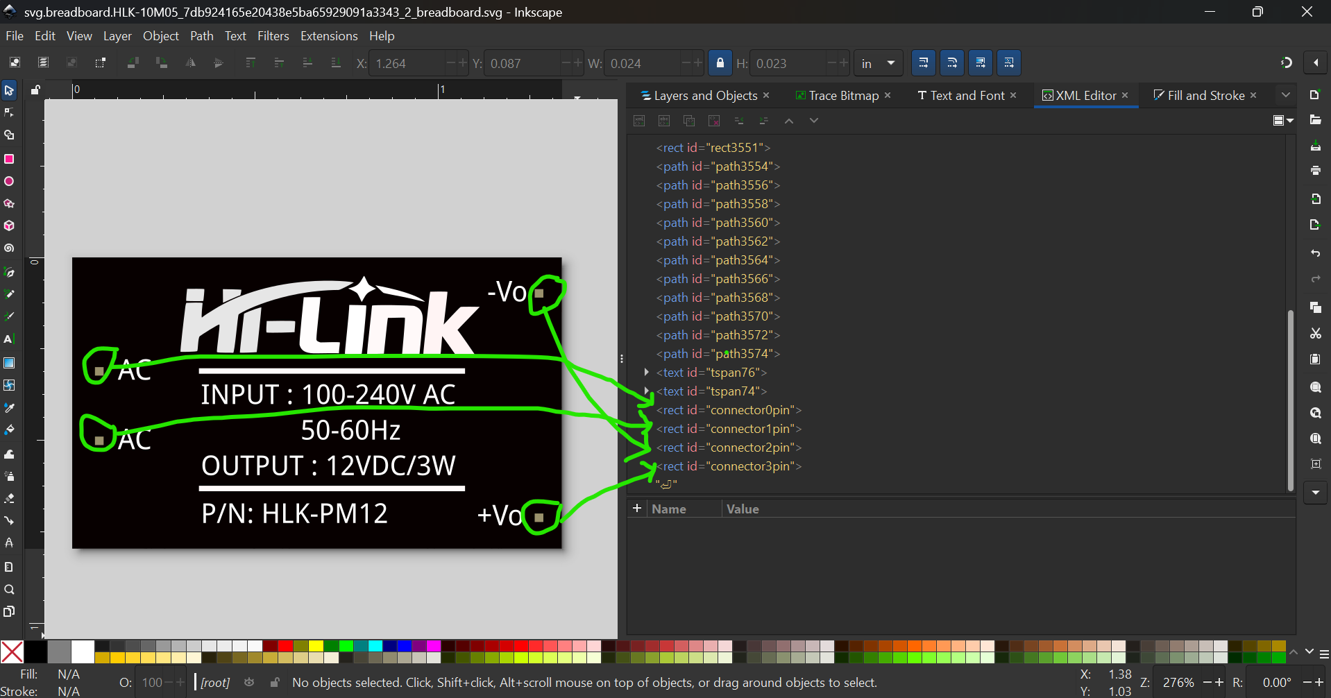
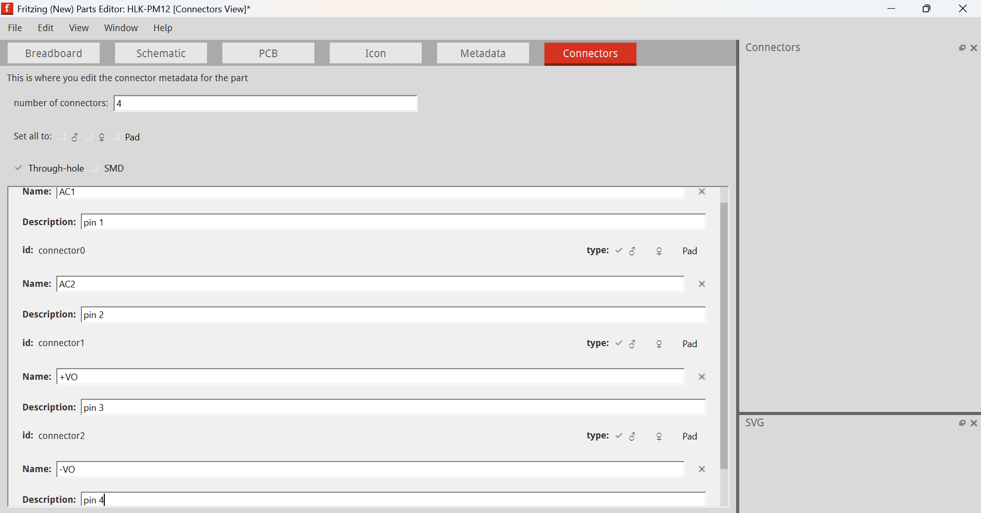
The connectors are in a mess, and typically we want to number them like this

Fill for connectors usually #9a916c so in XML editor change to
Renumber and reorder the connectors (delete connector1terminal too)
Then run the svg with @vanepp’s FritzingCheckPart.py which flags the following:
Modified 4: File
‘bb.svg’
At line 40
ReferenceFile
‘HLK-PM01-Breadboard.svg’
doesn’t match input file
‘bb.svg’
Corrected
Modified 1: File
‘bb.svg’
At line 180
Removed px from font-size leaving 77.626
Modified 1: File
‘bb.svg’
At line 184
Removed px from font-size leaving 74.9261
Modified 1: File
‘bb.svg’
At line 189
Removed px from font-size leaving 74.9261
Modified 1: File
‘bb.svg’
At line 194
Removed px from font-size leaving 74.9261
Modified 1: File
‘bb.svg’
At line 199
Removed px from font-size leaving 74.9261
Modified 1: File
‘bb.svg’
At line 204
Removed px from font-size leaving 74.9261
Modified 1: File
‘bb.svg’
At line 210
Removed px from font-size leaving 77.626
Modified 1: File
‘bb.svg’
At line 276
Removed px from font-size leaving 77.626
Modified 1: File
‘bb.svg’
At line 282
Removed px from font-size leaving 77.626
Warning 23: File
‘bb.svg’
At line 276
Key -inkscape-font-specification
value ‘Droid Sans’ is invalid and has been deleted
Warning 26: File
‘bb.svg’
At line 282
Apparant nested tspan which fritzing doesn’t support
If your text doesn’t appear in Fritzing this is probably why
Error 69: File
‘bb.svg’
At line 174
Found a drawing element before a layerId (or no layerId)
Then open the SVG and edit → select all → ctrl/cmd + g → XML editor → change id to breadboard
Then edit your old part with the new part editor and load this SVG

in there. The connectors have changed, so we have to change from

to
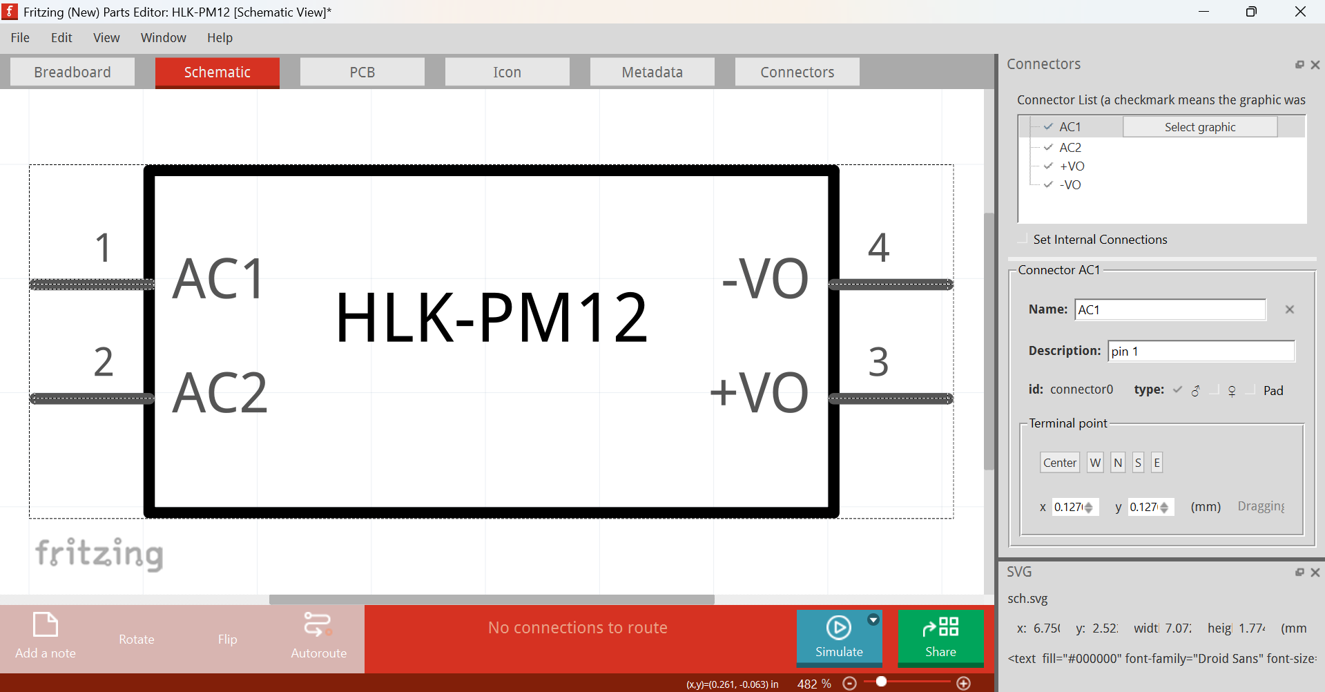
Schematic
The easiest is to redo the whole schematic with the schematic extension
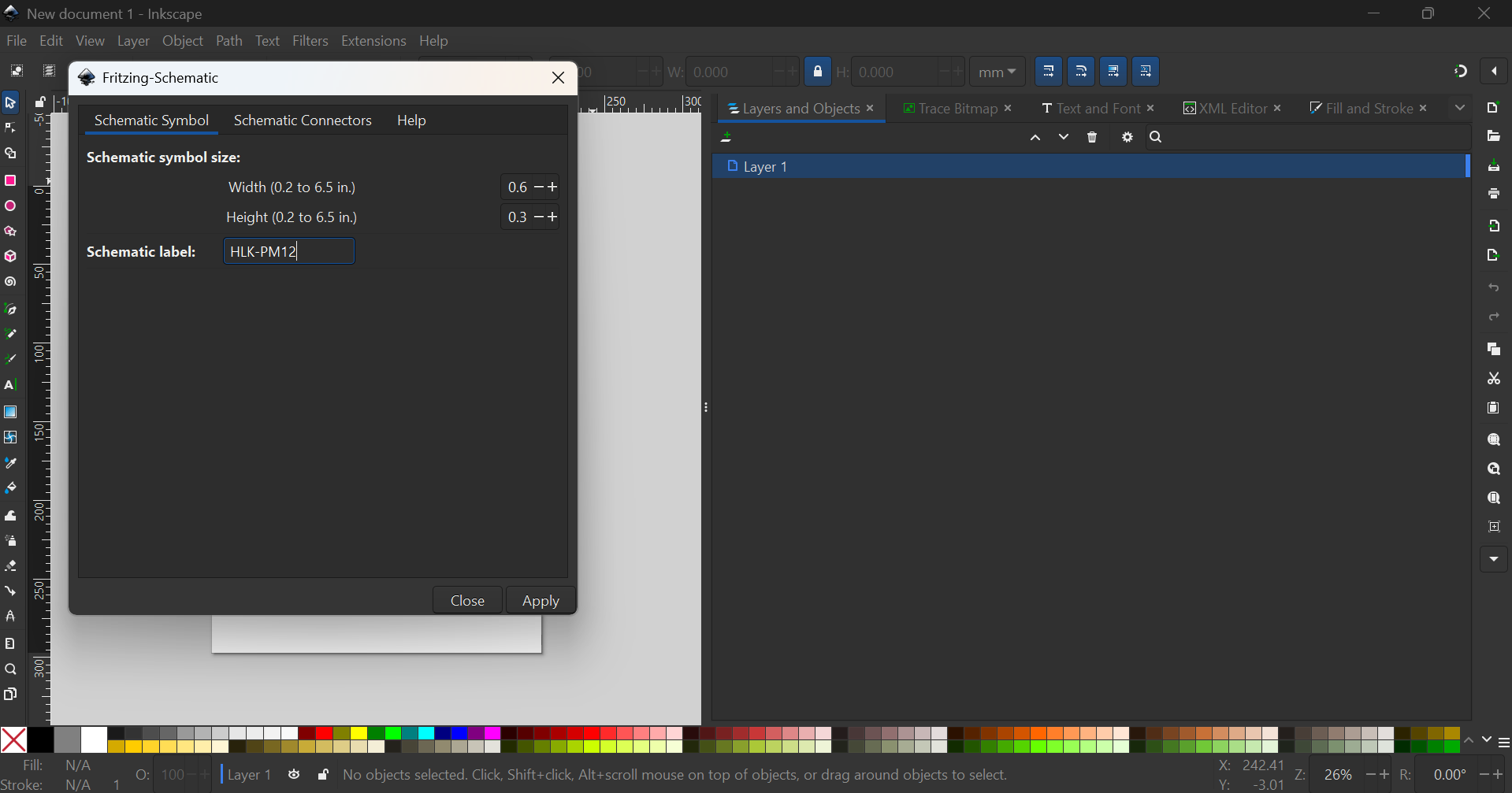
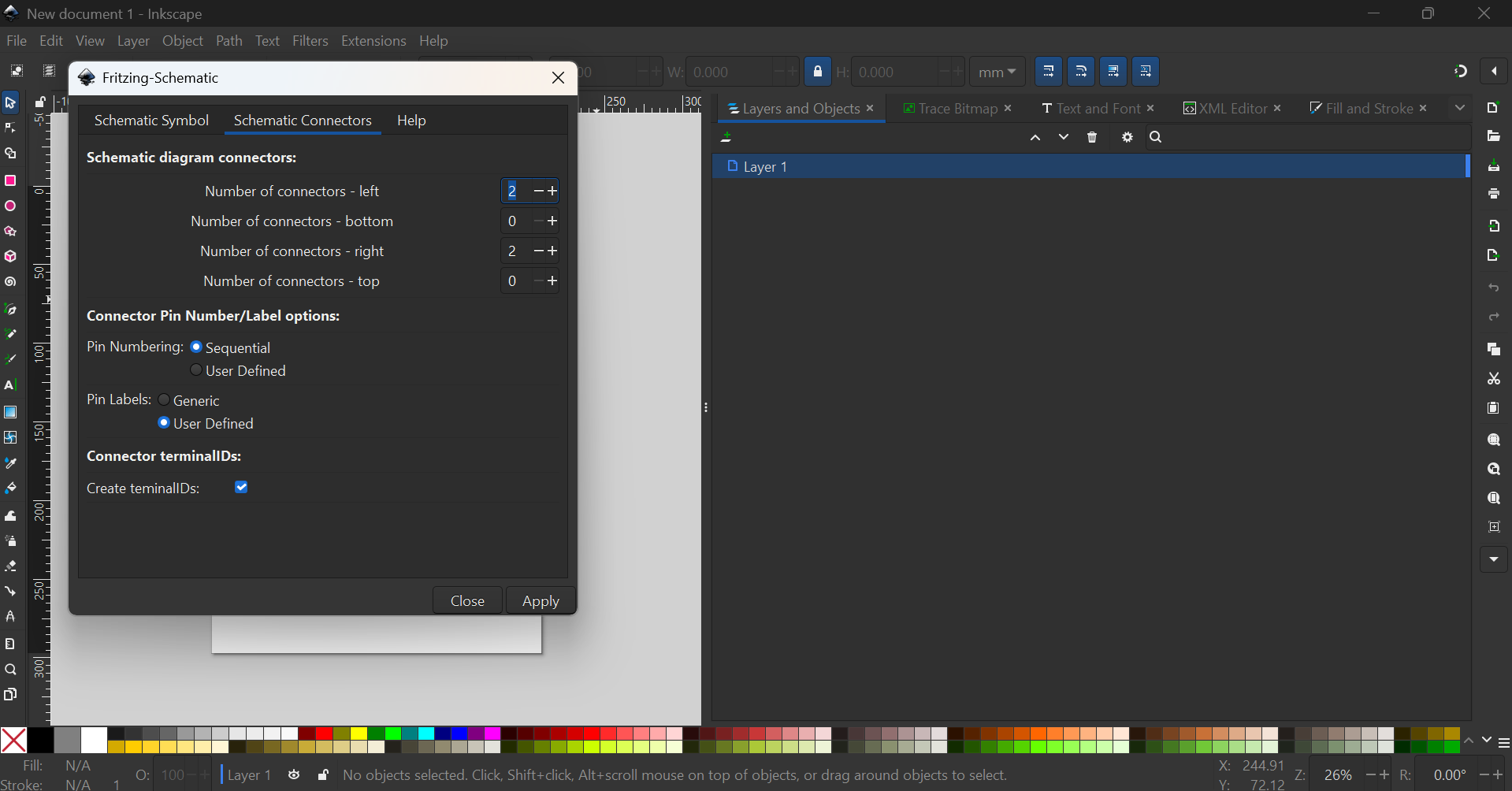
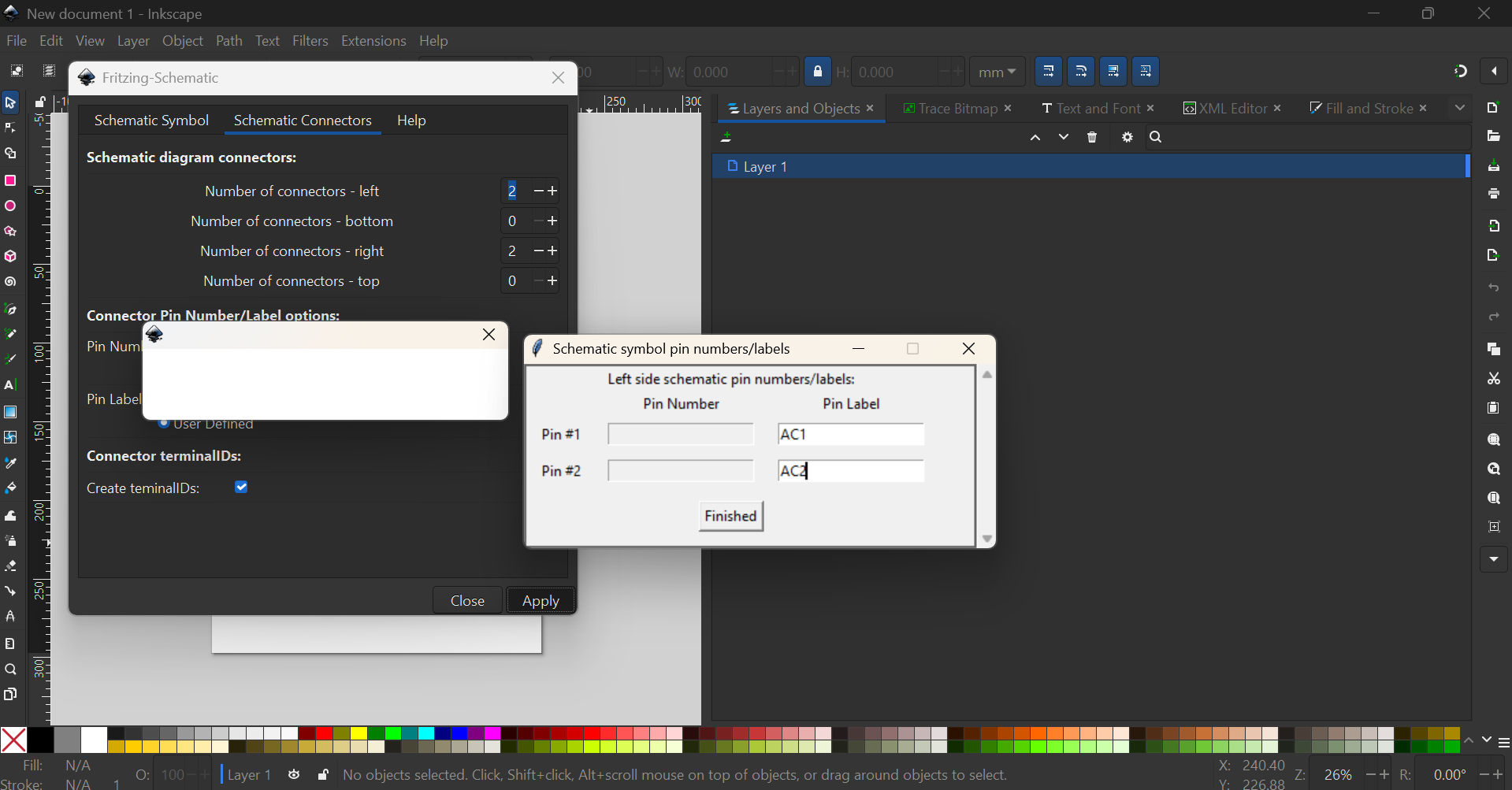

which will result in this SVG
![]()
PCB
Disclaimer: I assume the hole sizes are correct
So, the groups are wrongly configured
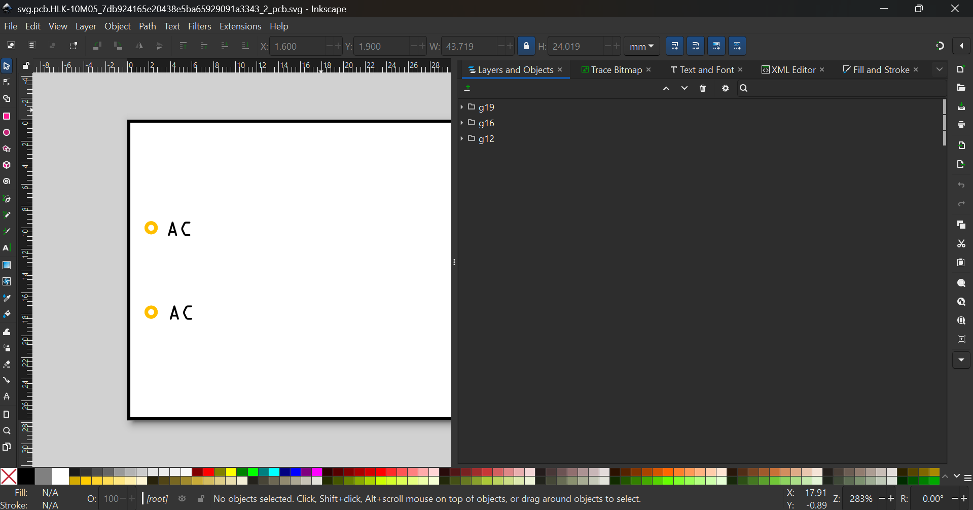
First, ungroup everything
Then delete the unused circles and the texts
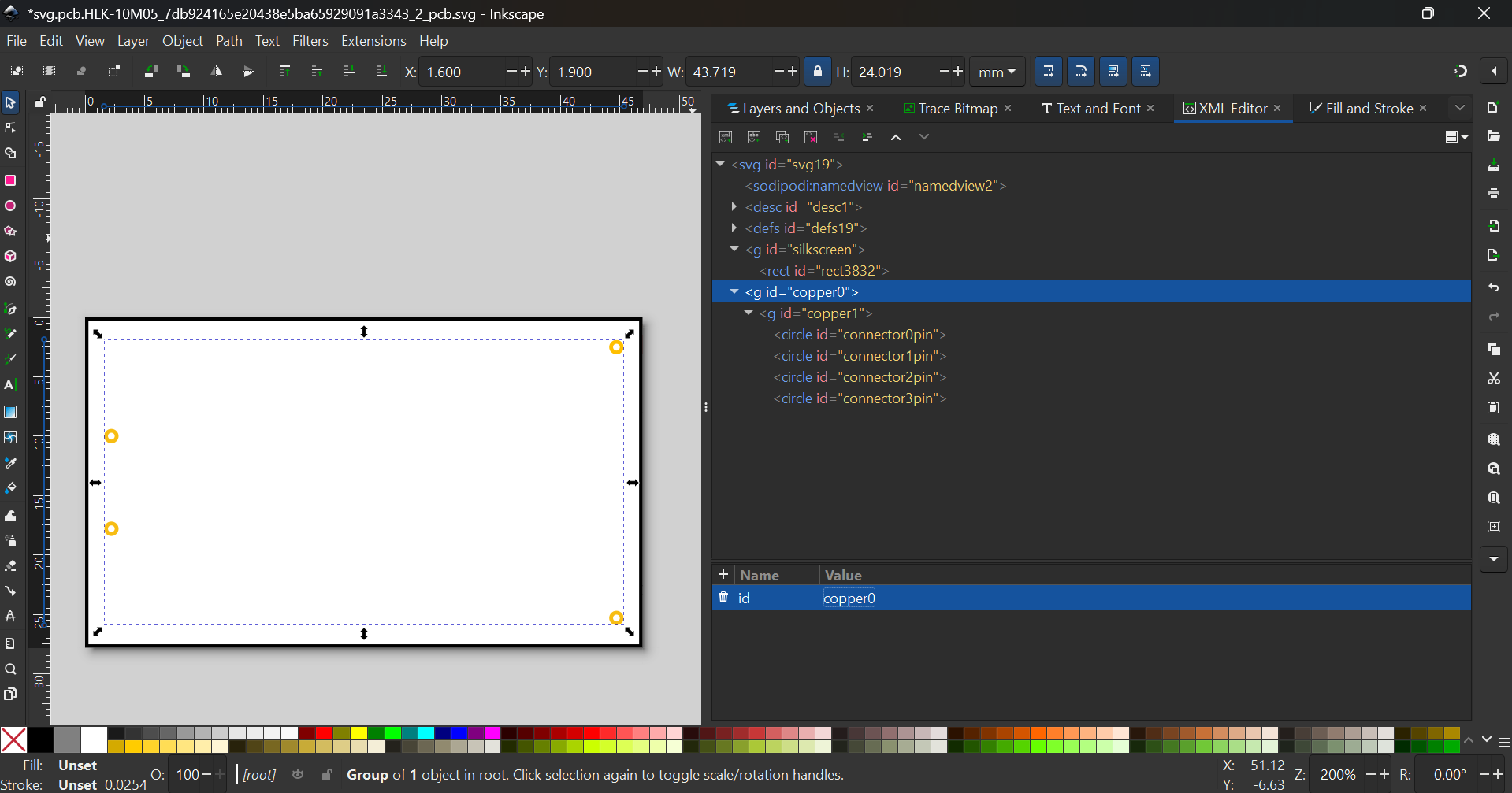
Group everything, then adjust the scale

and ungroup everything.
Group the rectangle, the connectors twice, and reorder/rename them, like this. Same thing, rename the connectors as necessary
You also have to change the stroke to #f7bd13 too.

HLK-PM12-fixed.fzpz (10.5 KB)