Your part has a few errors:
Breadboard View
Breadboard view has a lot of unnecessary details. Actually, just the text and the rectangles are just enough!
I also changed the fill of each pin to f7bd13. All the changes above (and lots more minor ones) turn out with this svg:

Schematic View
The wire terminates to the centre of the pin (due to the lack of terminalIDs) and the label is still IC(?)
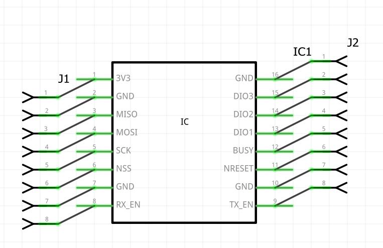
To solve the problem, use Randy’s Inkscape Extension
Installation:
Usage:
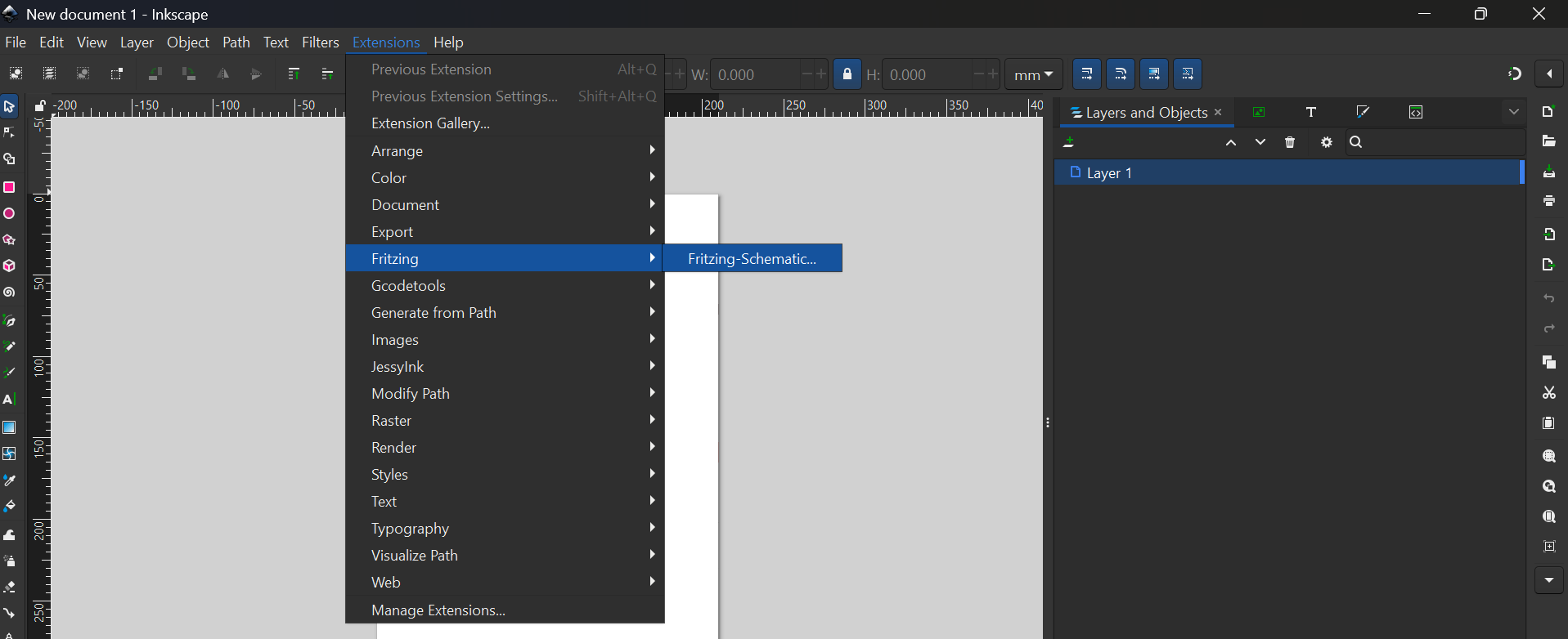
Start with a blank SVG, then Extensions → Fritzing → Fritzing-Schematic
Go to Schematic Symbol tab and set:
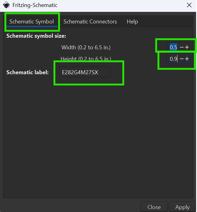
(note: there is an error in the image. The height should’ve been 0.7)
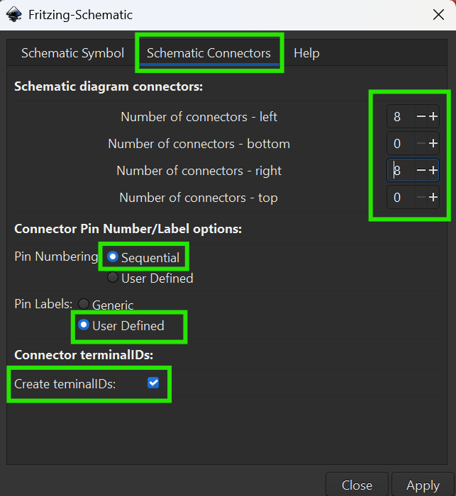
Go to Schematic Connectors tab and set:
Click apply, then:
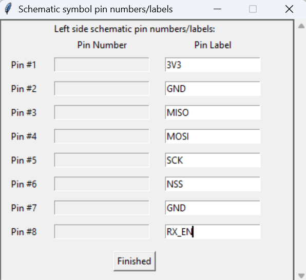
Pin #9: TX_EN
Pin #10: GND
Pin #11: NRESET
Pin #12: BUSY
Pin #13: DIO1
Pin #14: DIO2
Pin #15: DIO3
Pin #16: GND
Upon pressing “Finished”, you should get this:

PCB View
I don’t have time to create the PCB view for this part. It’ll be grateful if someone can help ![]()
Anyway, here’s the edited part:
Lora SX1280 - E282G4M27SX-fixed.fzpz (9.6 KB)