vanepp
January 25, 2023, 5:34pm
2
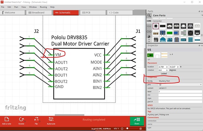
A number of problems in this part. Most layerIds are missing which means the part won’t export as an image, the family is still “Mystery Part” (which will cause issues if you change something in Inspector) and schematic is not correctly aligned to the 0.1in grid and doesn’t have terminalIds (which causes the wire to connect to the middle of the pin.)
This parts making tutorial covers everything I did here to correct this part:
Someone in this forum post
requested help to fix up a part. So while doing that I decided to record what I needed to do in order to fix the part to provide a tutorial to create new / fix broken parts. If you start from the Tarjeta S4A EDU.fzpz file posted in the above thread, you should be able to recreate my improved part posted in the same thread. I started by loading the original part in to Fritzing, that indicates breadboard is (at first look anyway) pretty good, but schematic and pcb are…
which includes using this Inkscape extension to correct schematic:
Hi all!
I have been working on an extension for Inkscape to create rectangular schematic symbol .svg files for use in Fritzing. I think I created a useful tool to speed up creation of schematic symbols, and now I want to share it with the community.
It’s available on github:
https://github.com/revolt-randy/Fritzing-Schematic-an-Inkscape-Extension.
To install:
In Inkscape, the edit menu → user preferences → system will have an option for ‘User extensions’ - allowing you to open the folder to…
Here is a corrected part
Akizuki-Denshi-AE-DRV8835-S.fzpz (12.3 KB)
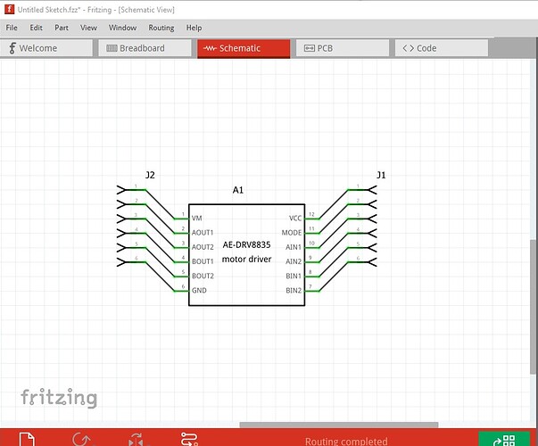
It has a new moduleId and file names and thus can be loaded alongside your original part for comparison. The new schematic looks like this:
Note the pin numbering has changed to the standard Fritzing layout so the two parts will not replace one another. Hope this helps.
Peter

