As I lately decided to merge this tutorial with Peter’s part creation series, I left the links behind. Never mind, I’ll just leave them there as a reminder.
In this tutorial, you are going to learn how to make Fritzing Parts.
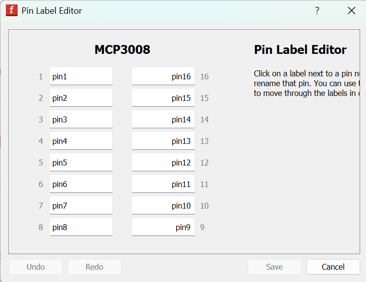
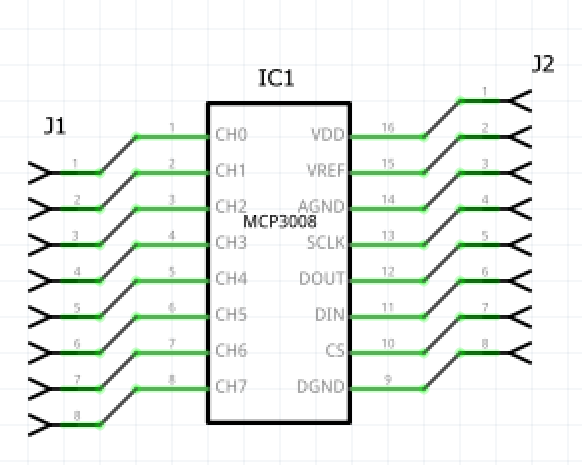
For the schematic view, the wire cannot terminate to the centre of the pin, and the label should not fly out of the box.
If your Schematic not work, please use Randy’s Inkscape Extension. Instructions are in the forum post
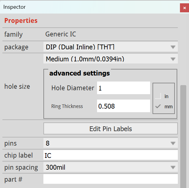
Note that you have to change the height to 0.9, and the width to 0.5 (or 0.6). Please also set the no. of left and right connectors to 8 (pins on each side)
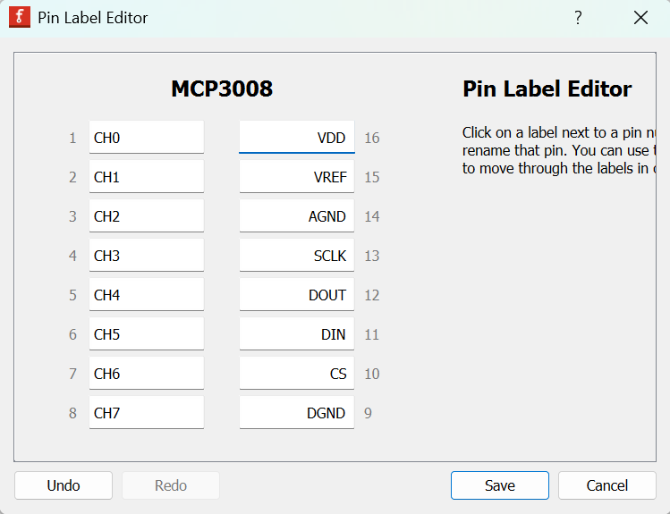
Model Answer
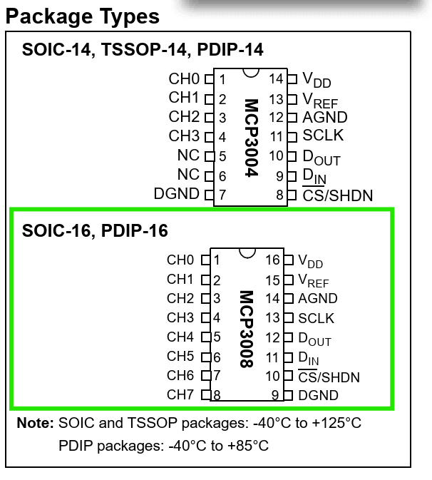
After following all the steps above, you will get a part like this: MCP3008.fzpz (7.2 KB)
I have changed the module ID of the part, so you can compare your part against mine.
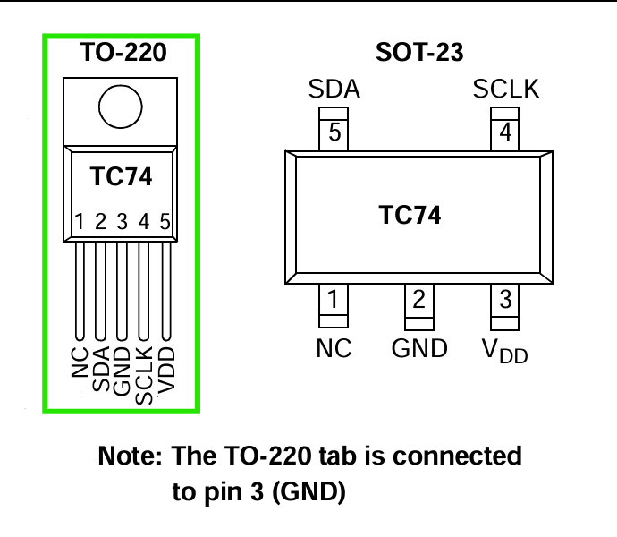
Chapter 1.2: ICs (TO-220 package)
A year back, I requested a TC74 part.
This time round, I decided to adopt the TO-220 Package Design from the Voltage Regulators Bin (not found in part versions before Fritzing 0.9.10)
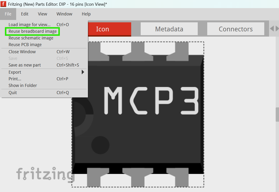
So I compiled some breadboard view SVGs (for your future use) and here they are (right-click on the image → Save as…)
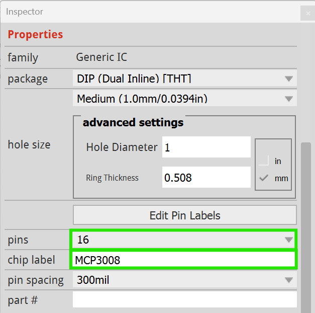
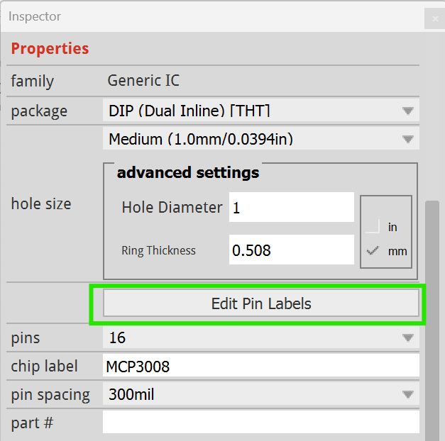
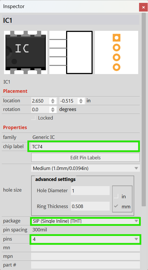
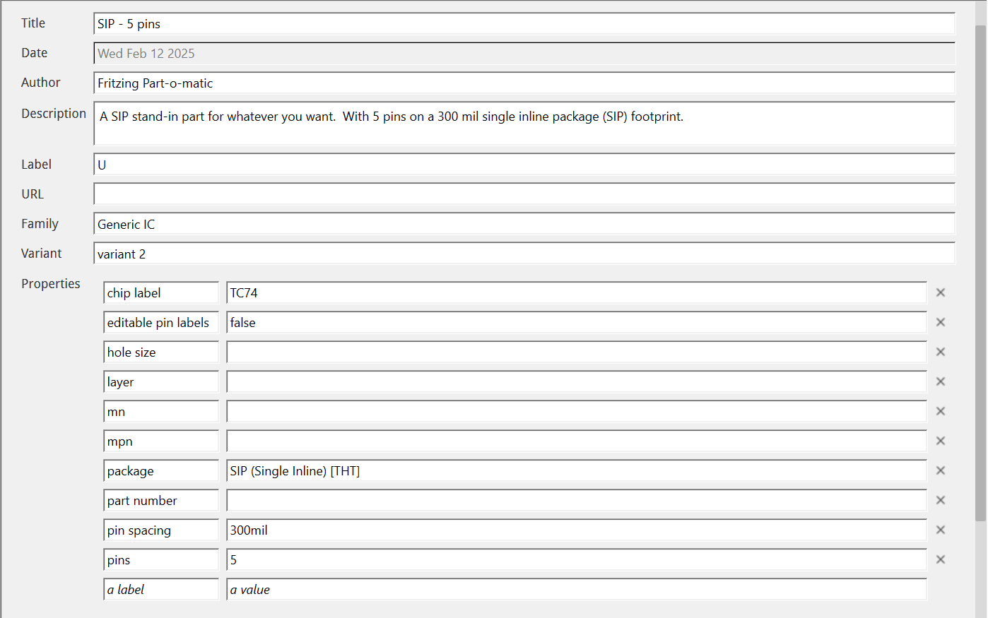
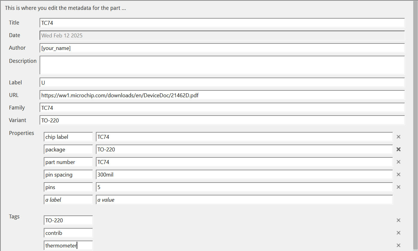
(Changes are boxed in green. Note that there is an error in the image. The no. of pins should’ve been 5. If you are making another IC, please change the fields above accordingly)
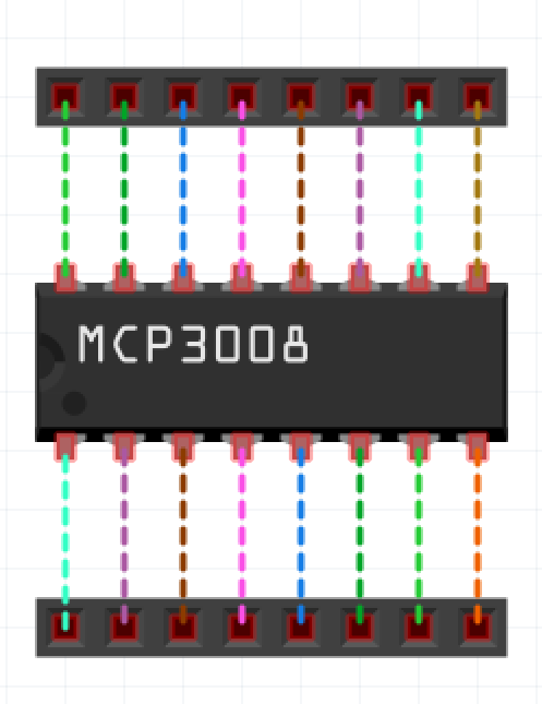
Breadboard View
Please download the SVG here:
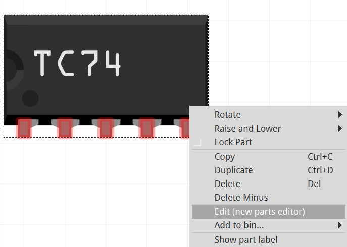
File → Load Image for View → Select .svg file → Open
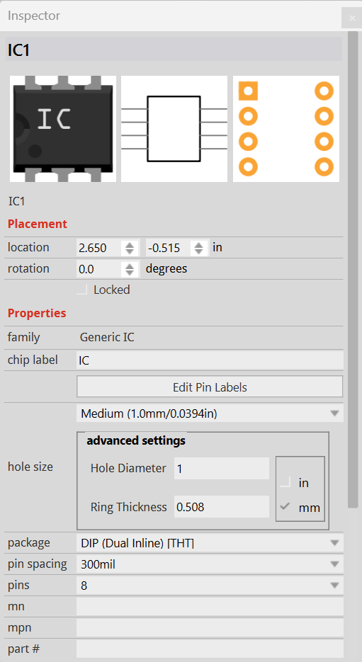
It is good practice to change the family from Generic IC first before loading image for view so that the Part-o-matic will not get confused (I think a few users experienced schematic view problems because of this!)
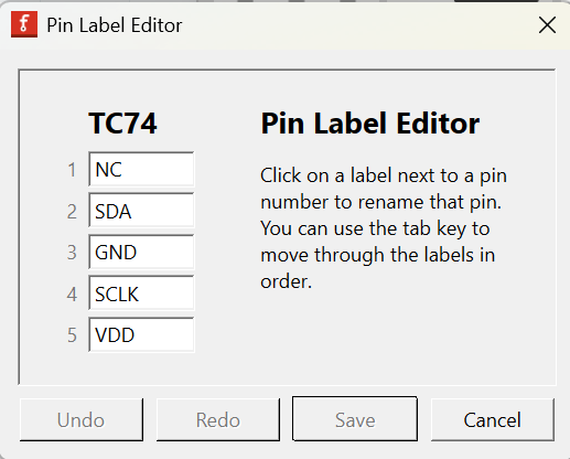
Then check if the pins are configured correctly.
Schematic View
I think the parts factory’s schematic looks fine, so you can use it.
Once done, save the part. Then follow the testing steps above.
Remember: The wire should never terminate at the centre of the pin in the Schematic view. Your schematic cannot lack terminalIDs (if you’re using the extension.)