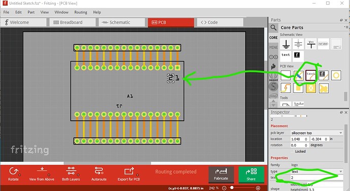
It will work with text on the silkscreen layer in pcb (the text will appear on silkscreen on the pcb.) The problem is that if the user doesn’t want the printing on the pcb for any reason, with the text in the silkscreen layer in the pcb svg, they need to make a new part to remove the text. If the text isn’t in the part’s silkscreen layer in the part it can be added to the sketch (via core parts->pcb->text in Inspector) without needing to modify the part, and therefore that is the recommended way to make parts. As noted the text on silkscreen layer works fine though.
As long as all the ground pins on the board connect to each other internally to the board (which is normally but not always the case), then they should be in a bus in Fritzing.
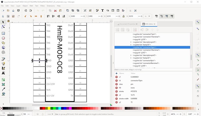
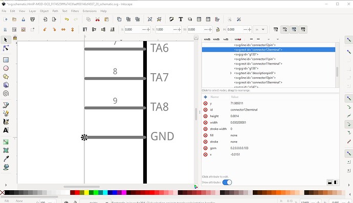
To Fritzing all pins in a bus are the same so it will connect to the ground pin closest to the connection. One wrinkle is that in schematic (which is an abstract view) only one connection to a bus is allowed. That means if you do what I usually do and have schematic match breadboard (i.e multiple ground pins) sometimes Fritzing will not make a connection to a pin if there is another connection already made. One solution to this (which I don’t particularly like personally) is to overlay all the common pins like this:
current:
new:
Here all of pin/terminal 10, 11, 12 are in the same place (overlaid on pin 10) and thus will connect to a common point. As noted I don’t like this and don’t often do it.
Yes. If you clone the Fritzing-parts repo on github and add your part and make a pull request it will get added to core parts (assuming it passes QA!) in due course.
It is unfortunately not all that user friendly. While I normally use cygwin it should be possible (although I haven’t done it) to run it from a native python 3 install. You would probably need to use pip to add the lxml module though. That doesn’t make it much more friendly though, but I don’t know of a way to do that. Here is what FritzingCheckPart has to say about the new version (still some problems!)
Warning 36: File
‘part.HmIP-MOD-OC8_1ed0c3cff7aa35a4e5bd1c4caa11b240_2.fzp.bak’
Connector0 doesn’t exist. Connectors should start at 0
Warning 32: File
‘svg.breadboard.HmIP-MOD-OC8_9174525ffffa7433faeff00146cf4557_20_breadboard.svg.bak’
At line 3
Scale is not the desirable 1/1000 ratio from width/height to
viewBox width/height.
…
Error 69: File
‘svg.schematic.HmIP-MOD-OC8_9174525ffffa7433faeff00146cf4557_20_schematic.svg.bak’
At line 13
Found a drawing element before a layerId (or no layerId)
Error 77: File
‘svg.schematic.HmIP-MOD-OC8_9174525ffffa7433faeff00146cf4557_20_schematic.svg.bak’
At line 172
terminalId connector0terminal can’t be a g as it won’t work.
Error 18: File
‘part.HmIP-MOD-OC8_1ed0c3cff7aa35a4e5bd1c4caa11b240_2.fzp.bak’
Connector connector23terminal is in the fzp file but not the svg file. (typo?)
svg svg.schematic.HmIP-MOD-OC8_9174525ffffa7433faeff00146cf4557_20_schematic.svg.bak
Error 18: File
‘part.HmIP-MOD-OC8_1ed0c3cff7aa35a4e5bd1c4caa11b240_2.fzp.bak’
Connector connector24terminal is in the fzp file but not the svg file. (typo?)
svg svg.schematic.HmIP-MOD-OC8_9174525ffffa7433faeff00146cf4557_20_schematic.svg.bak
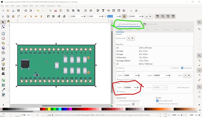
In order, the pins don't start at 0 they start at 1 still. connector0terminal isn't actually used so it being a group (while incorrect) is irrelevant. The scale isn't as recommended. This will work fine (and thus is only a warning) but in Inkscape is also easy to fix (assuming Inkscape at least!)
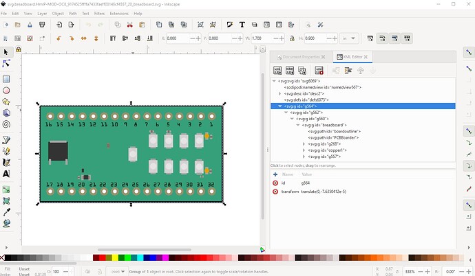
initial:
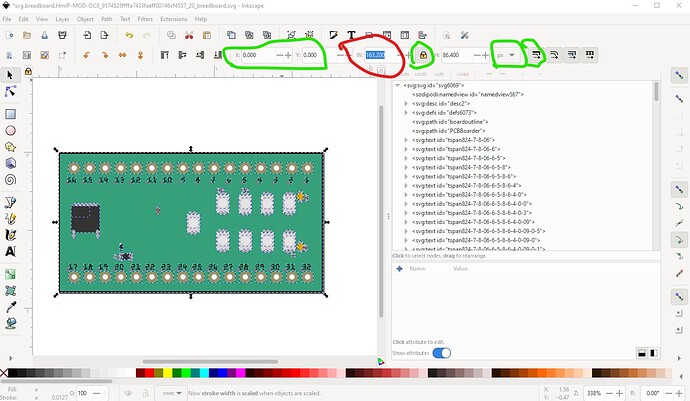
then ungroup everything which will remove most transforms. Now Edit->select all, then check that the starting x and y are both 0 (do Edit->resize page to selection if not!), lock width to height, set dimensions to px (finest resolution) and record the current width value (163.200px in this case) and set scale stroke width (which I normally leave off.) like this:
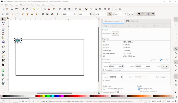
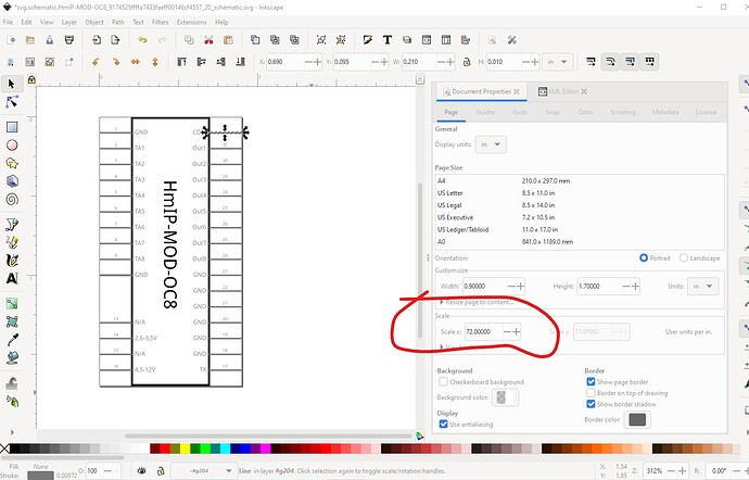
now in Document Properties (this assumes you are using Inkscape 1.1.2, earlier versions are different!) set the scale from the current 72 to 1000
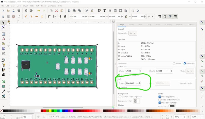
to get this
now set the width to the previously saved width like this:
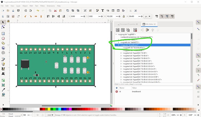
Now you need to remake the layerId by grouping the svg and setting the group name to breadboard like this:
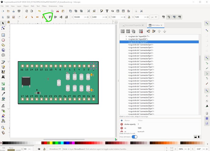
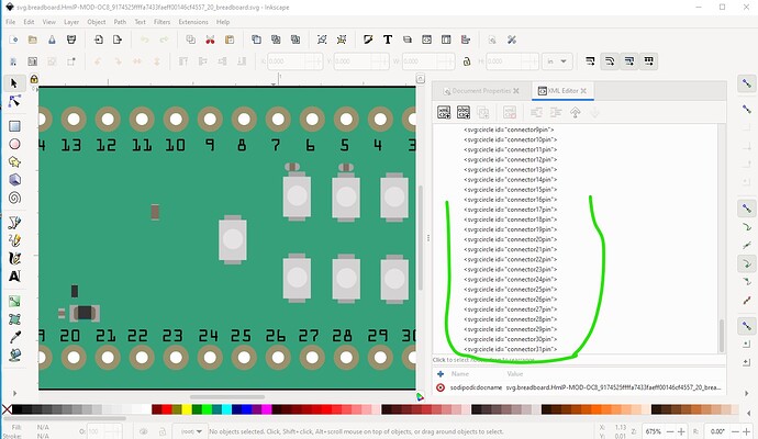
now I am going to arrange to renumber the pins. To do that I move them in order to the bottom of the svg in xml editor like this:
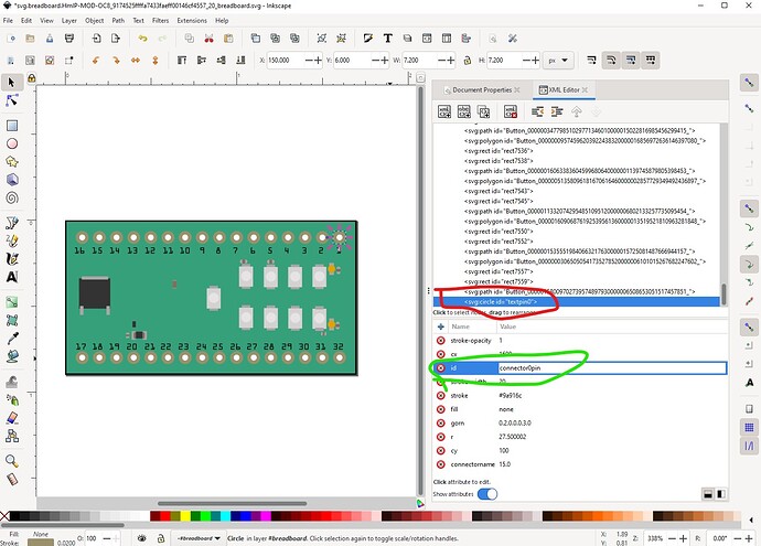
This moves the pin to the bottom of the svg like this:
on the way by I changed the name of connector0 from textpin0 to connector0pin (the renumber script is looking for connectorpin0 to start renumbering the pins!) Then do the same for all the rest of the pins to get this
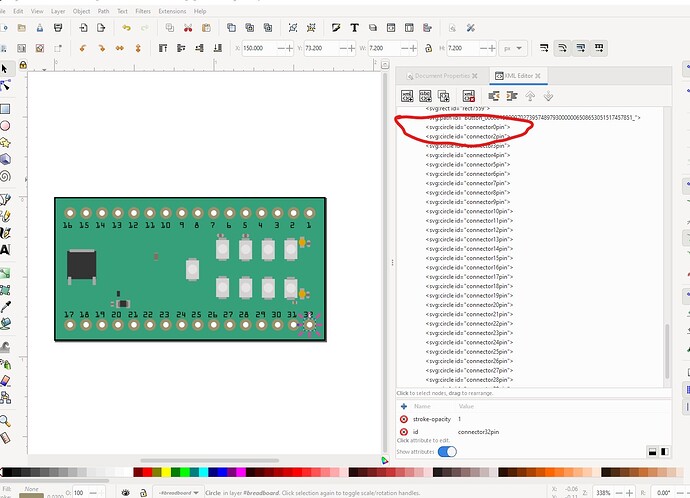
note the first two pins are out of sequence (connector1pin is missing.) Now I save the svg in Inkscape and run (so far unpublished!) python script which renumbers the svg like this:
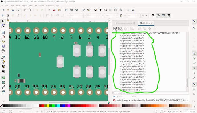
now the pins start at connector0pin and run sequentially to connector31pin as they should. We still need to change the other svgs and the .fzp file, but for now on to schematic. It has a variety of problems. Its scale is wrong
the pin is too long (0.2in instead of 0.1in and the color is wrong (#787878 insteadn of #555555), the text sizes look to be incorrect and the incorrect color as well. The easy fix to this is make a new schematic with Randy’s Inkscape extension available here:
start with a blank canvas (here I started from the schematic svg and deleted everything)
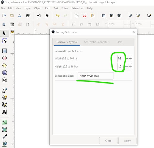
then start the extension and set the parameters
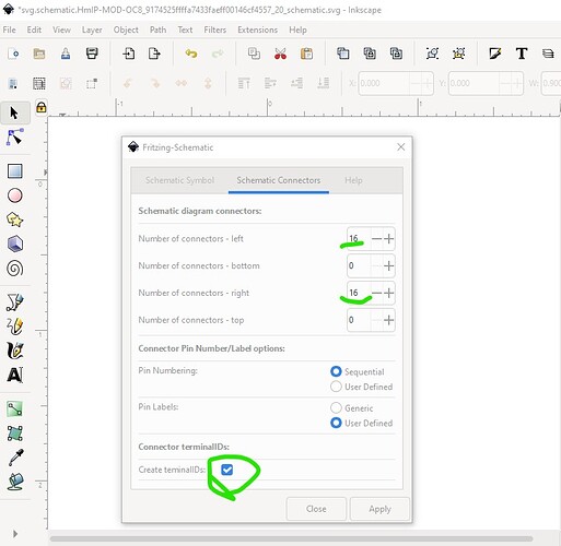
Here I set the height to 1.7inches because there are 16 connectors on left and right. A width of 0.8in is about correct and set the label from the original schematic as the new label name. Now switch to the connections tab and set our connections.
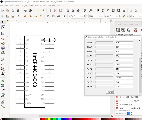
Here I set 16 connections on left and right sequential pin numbers and user defined labels as well as create terminalIds. Now hit apply and set the label names like this:
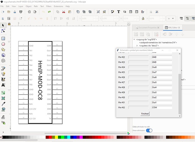
Here I copied the labels on the left from the original schematic svg. Once all the pin names are entered click finished to get to the other side like this (note that on the right side the pins start from the bottom not the top!)
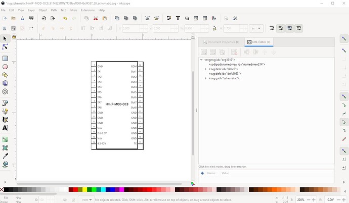
now click finished and it populates the svg like this:
and schematic is now complete ready for use.
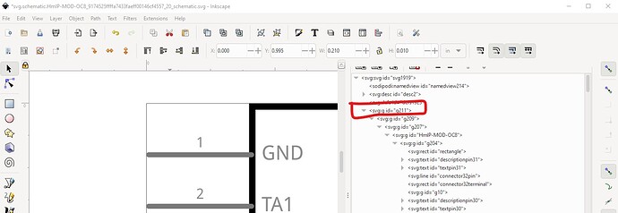
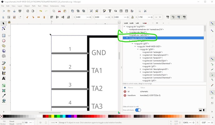
In the original schematic the no schematic layerId is important because your part won’t export as an svg or other image type (it will be blank in the export!) that can be fixed by grouping the entire svg and naming the group schematic like this (or by using the new schematic svg which is what I will do!):
initial
fixed
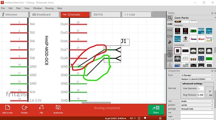
missing terminalIds cause (and can be tested for) this:
Here pin 23 is missing its terminalId and thus connects to the middle of the pin (which is incorrect!) pin 22 has a correct terminalId and is thus correct.
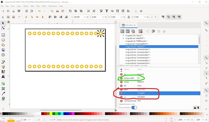
Now on to pcb. Again the scale is incorrect, so set it to 1000 as with breadboard. Then change the border outline stroke-width to 10, change textpin0 to connector0pin to establish pin0 for the renumber. As well change the pad radius from the current 27.5 to 29 to make the hole be 0.038in suitable for a 0.1in header(0.032in is probably too small!) for all pins (I will make this change in the svg with a text editor!) Also increase the size of the rectangle on connector0 to a stroke-width of 20 and height and width of 0.078in and set the x and y coord to be the same as connector0pin so the two are aligned.
As noted I deleted the text to allow for users that don’t want text on the silkscreen, you can add it back in if you choose. Then ran the script that renumbers the pins in the svg and pcb is done. Now on to the .fzp file.
First I changed the Fritzing version to 0.9.10, then deleted the connectors (because they have been renumbered) and replaced them with a set correctly sequenced generated by a script I have. Now I need to set the description fields and adjust the bus definitions to match the new pin numbering and add a label of “A” (for assembly) and we are done. Since the board silkscreen no longer has numbers you need to add them to the sketch like this:
The text is set by typing in inspector on the right, font size can be adjusted just below the text field. It means this must be done in every sketch though so you may want to leave them in silkscreen. One additional issue if you are not using FritzingCheckPart.py, one of the things it does is remove the px from font sizes. Inkscape adds them to be CSS compliant but Fritzing objects to them and will sometimes set the font size to 0 ( making the text unreadable) or a large value (making the text too large.) You can remove them by editing the svg with a text editor and doing a global replace of px with “” or use @just_randy 's new Inkscape extension which removes pxs Fritzing-Fix text but when I checked it doesn’t look like it has been released yet (I have a review copy), so you may need to ask him about it. Hope this helps.
Here is a part with the above changes made in it.
HmIP-MOD-OC8_v0-10.3.fzpz (24.7 KB)
Peter
