Ah! For a schematic the svg is also incorrect. For schematics the best starting point is this Inkscape extension as it will create a correctly formatted svg that you can change:
at the correct scale with dimensions in inches. In this case you will need to change the default (which is a box with pins) to have the correct layout of the relay pins but if you start from that svg you will have the correct layout of the svg. You should ungroup the svg before making changes, modify it to what you want, then do an Edit-> select all then Object>group and name the resulting group to “schematic” to have the correct layerId.
edit:
Here is a schematic svg made with the Inkscape schematic extension. Started from your original svg
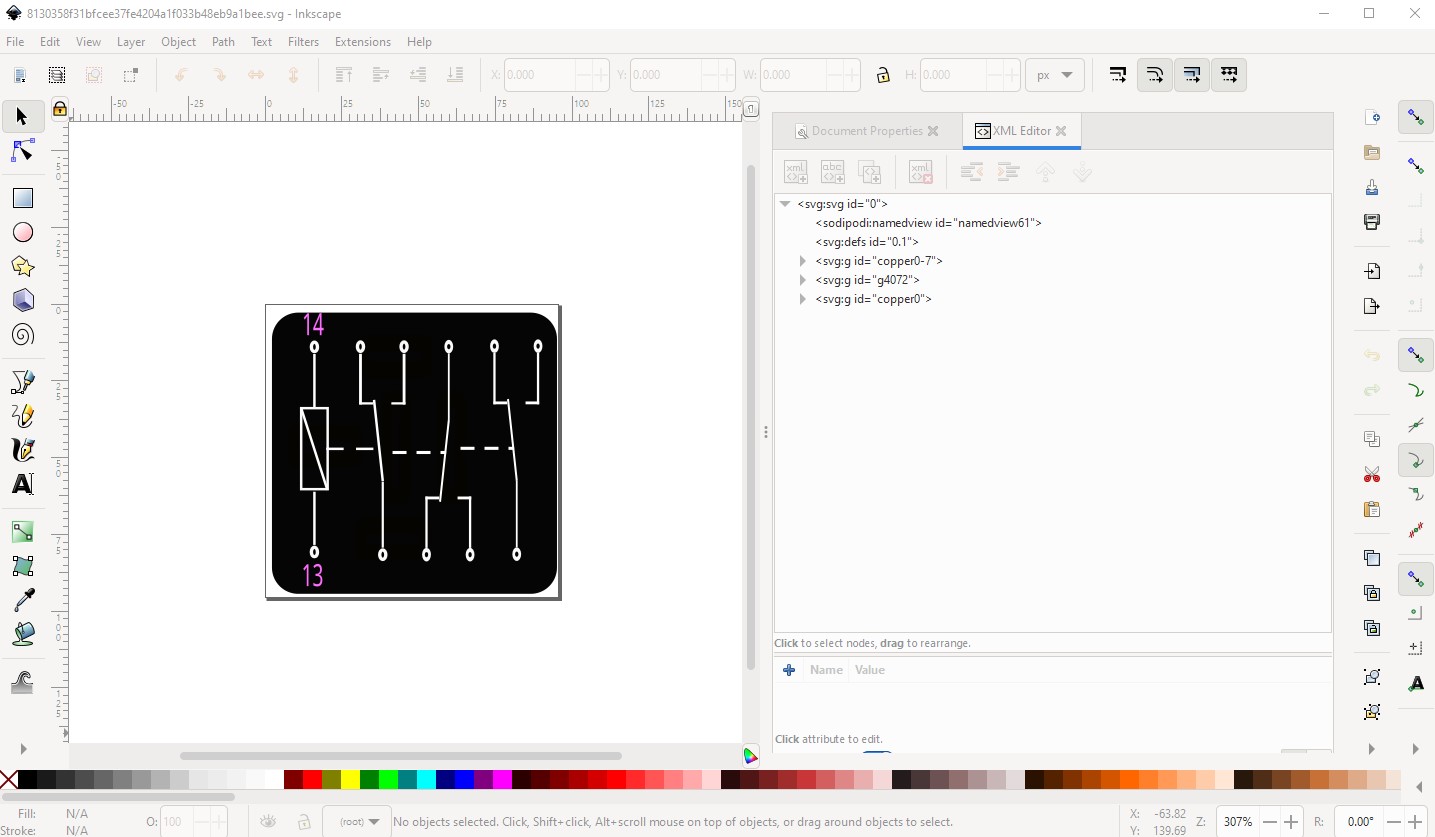
then deleted everything

and started the fritzing->fritzing-schematic extension in Inkscape
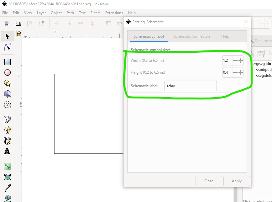
here I cheated (I had to redo this after making it too narrow the first time!) to get the correct length and width parameters. Since I don’t know the part number of your relay I just used relay.
Then I specified 5pins on the bottom and 6 pins on the top.
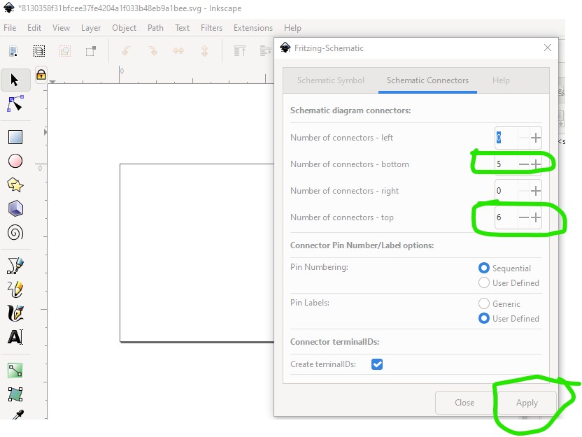
then hit apply which brings up the pin number windows
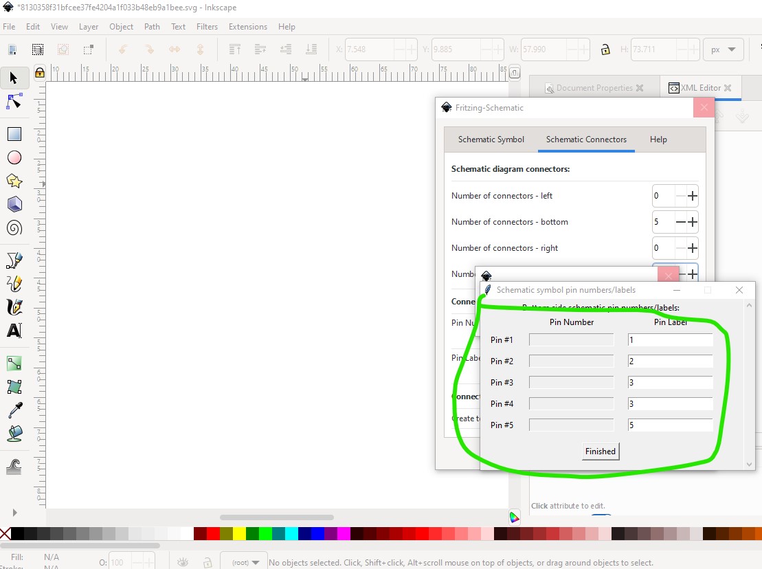
here I just used the pin numbers as we will delete them later.
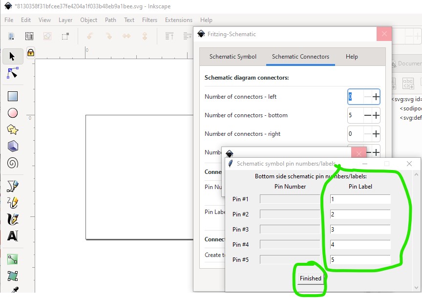
Then hit finished and do the same for the top connectors:

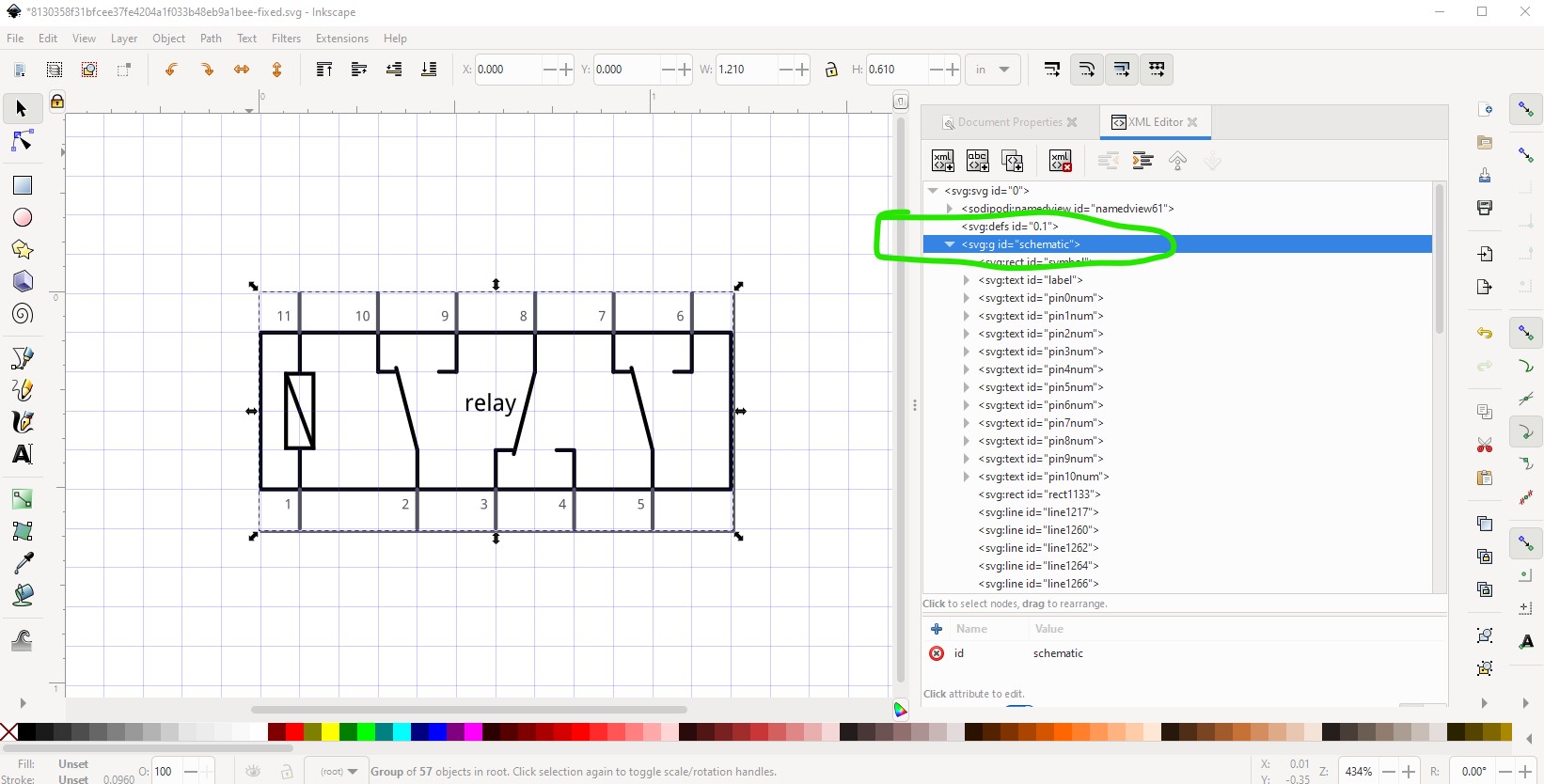
then hit finished and the extension creates the svg in the correct scale, format and colors to meet the graphics standards and looks like this (which needs some editing in this case!)

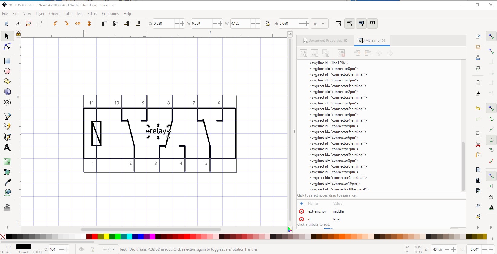
first select group schematic in xml editor and either hit cntrl-G or Object->ungroup to ungroup the svg to make changes.
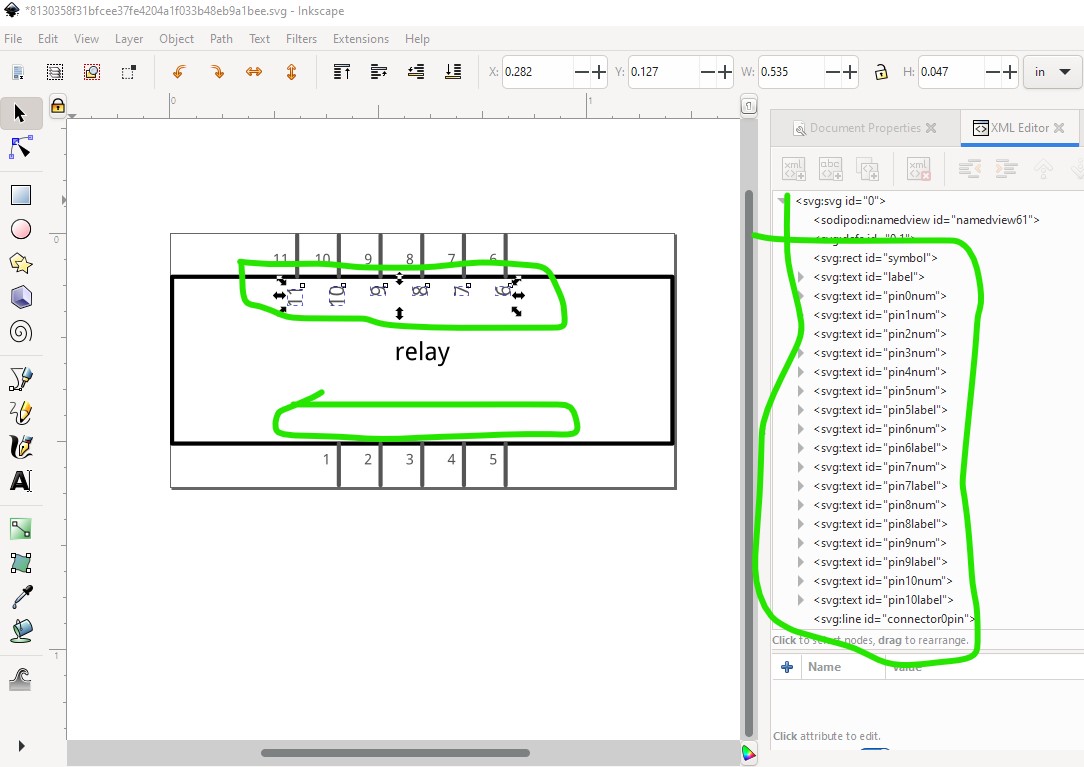
first delete all the pin names we added as we don’t want them in this case. Select the entire first pin with a select box (to get both connector0pin and connector0terminal) and use the tool bar x decrement button to move the pin to the left edge of the rectangle (because the tool bar is set to inches, this will maintain the correct 0.1in spacing!)
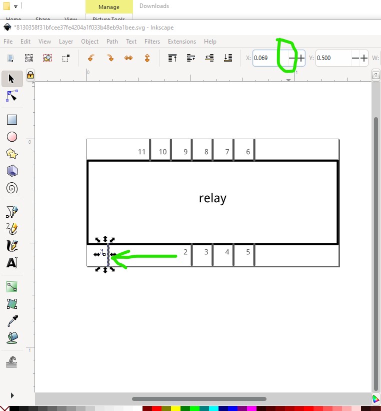
now do the same to all the rest of the pins to make it look like this (we will add the green lines in a bit!)
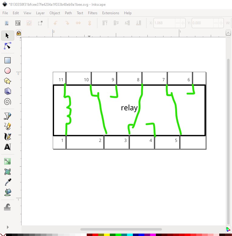
now add the lines to duplicate the original svg like this
then do an Edit–>select all, Edit->resize page to selection and Object->group to set the layerId. Rename the resulting group “schematic” so set the correct layerId then File->Save as and select save as plain svg then save the svg.
That creates this svg which should load correctly in parts editor. You may need to adjust the pin designations in the fzp file as this svg starts at connector0pin as pin 1 up to connector10pin for the last pin on the top left which may not match your part. You will likely also want to change the label relay to something more appropriate. Below is the above svg:

Peter