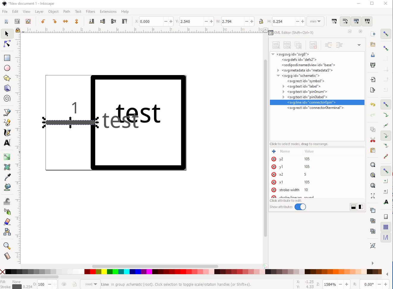
The most likely answer is a non obvious one: do you have a terminalId defined and is it on the end of the line that is the connector? For example if you only have this (just the pin):
Fritzing will connect the wire in the center of the pin, then align the grid to the “terminal” (the center of the pin) and thus schematic will be offset 0.05in in x. With both the pin and terminalId set and correctly placed alignment will be correct. There is an Inkscape extension available here:
this is what I created the above example in. It creates correctly configured (correct scale, correct colors and terminalIds as long as you remember to tick the create terminalId box) schematic svgs. As well here are a couple of part making tutorials (and parts making is complex!) that apply to the current Fritzing versions (many of the rest are for older versions and may not be entirely correct anymore.)
Hope this helps, if not please upload the sketch that is not working (it will include your custom part as part of the sketch) and one of us will tell you what is wrong. Upload is 7th icon from the left in the reply menu and you want the .fzz file for the sketch.