I have made the mistake of electing myself “somebody” (as in “somebody should make a parts creation tutorial”) again. As punishment for this rash mistake, a single “here is how I fixed up this part” post has turned in to (so far ![]() ) 5 posts. These first three are infrastructure type posts that should be useful standalone. This one covers rescaling a drawing using Inkscape. It is being posted first because the real first document Configure Inkscape refers to this document and I needed the forum url to include. Such is life.
) 5 posts. These first three are infrastructure type posts that should be useful standalone. This one covers rescaling a drawing using Inkscape. It is being posted first because the real first document Configure Inkscape refers to this document and I needed the forum url to include. Such is life.
How to rescale a svg file to have the appropriate scale for Fritzing using Inkscape. First download this svg to work on. Note due to the fact the forum has trouble with svgs, this svg has been renamed to .fzp (which the forum uploads without trying to render.) So to get the svg download this file, then remove the trailing .fzp extension to leave you with the svg file.
Inkscape-config-schematic.svg.fzp (2.0 KB)
After you download this, remove the trailing .fzp from the filename. The forums try and render svg files, and often fail with valid svg files. It will however load a .fzp file that is really a svg file without problem.
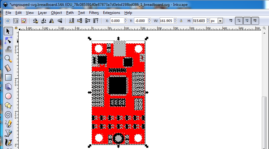
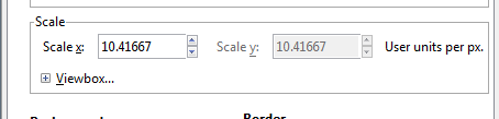
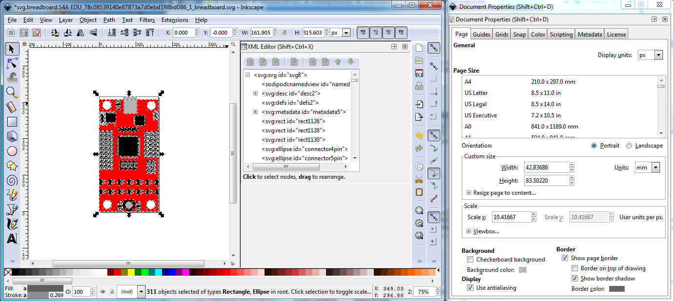
I started with the ‘svg.breadboard.S4A EDU_78c08539140e87873a7d0ebd198bd086_1_breadboard.svg’ file and loaded it in to Inkscape (which I used for this entire project, if someone would like to modify this post to use Illustrator, Coral Draw, Gravid, or one of the other svg editors that would be much apperciated!) as I use Inkscape to make Fritzing parts rather than one of the others. That indicated a problem, the scale is wrong, in Document Properties->Scale->Scale x:, the scale is 0.26458 rather than the desireable for Fritzing 10.41667 (which sets the view box to the desired 1/100 scale specified in the parts file format at
which you should read before and during making parts.

To correct that it is necessary to ungroup the entire svg so in Inkscape’s xml editor (Edit->XML Editor) select the g14 group and hit cntrl-shift-g (keyboard shortcut for ungroup) multiple times to ungroup. That finally produces path819 which if you do edit->select all will show as a 20in by 20in invisible rectangle which serves no purpose so delete it. Now do Edit->select all and then Document Properties->Custom size->Resize page to content->Resize page to drawing or selection. This is a very common sequence in Friting part making. It should be the last thing you do before re grouping the part, because it resets the view box and origin to the bottom left of the part and not doing it will sometimes cause scaling or offset problems in Fritzing. Now select group g1711 (the rest of the current part) and hit cntrl-shift-g multiple times again until there are no more groups in the image. Note for a large complex part this can take a lot of time and Inkscape will appear to hang while it does the calculations (removing the transforms from the document) be patient, it will usually eventually complete. You should end up with a document that looks like this:
ungrouped-svg.breadboard.S4A EDU_78c08539140e87873a7d0ebd198bd086_1_breadboard.svg.fzp (93.0 KB)
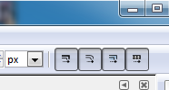
First insure that Edit->preferences->Behavior->Transforms->Scale stroke width is ticked (the easy way to do that is via the tool bar rather than the preferences menu):
Wrong (scale stroke-width disabled):
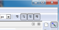
Right (scale stroke-width enabled):
Now we are going to rescale the document to the desired scale. To do so Edit->select all, then record the starting coordinates (with the tool bar set to px for maximum resolution) from the Inkscape tool bar here:
x 0 y 0 w 161.905 h 315.603 in this case.
Now with the Edit->Select all still selected change the scale from 0.26458
to 10.41667
Clicking on the image in Inkscape will cause the scale to take effect which looks like this:

you will likely need to click Edit->select all to reselect the now invisible (due to small size) document. Now to complet the rescale we need to set the tool bar back to the original settings.
set x 0 y 0 w 161.905 h 315.603 in the tool bar. Note some times (the conditions for which I don’t know, but think involve rescaling elements with stroke and non zero stroke width) the x or y origins will change along with the w and h and you need to reapply the starting coords several times until the end result is the tool bar is set to x 0 y 0 w 161.905 h 315.603. That did not occur in this instance, the document resized correctly the first time. If anyone know why this is and how to avoid it I would really like to know. The end result should look like this:
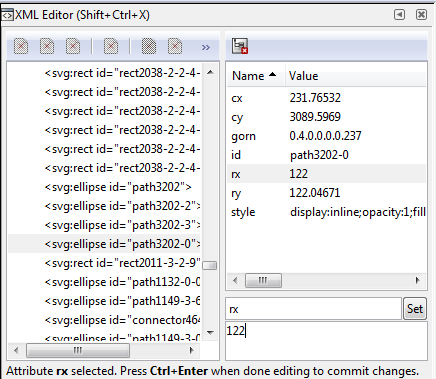
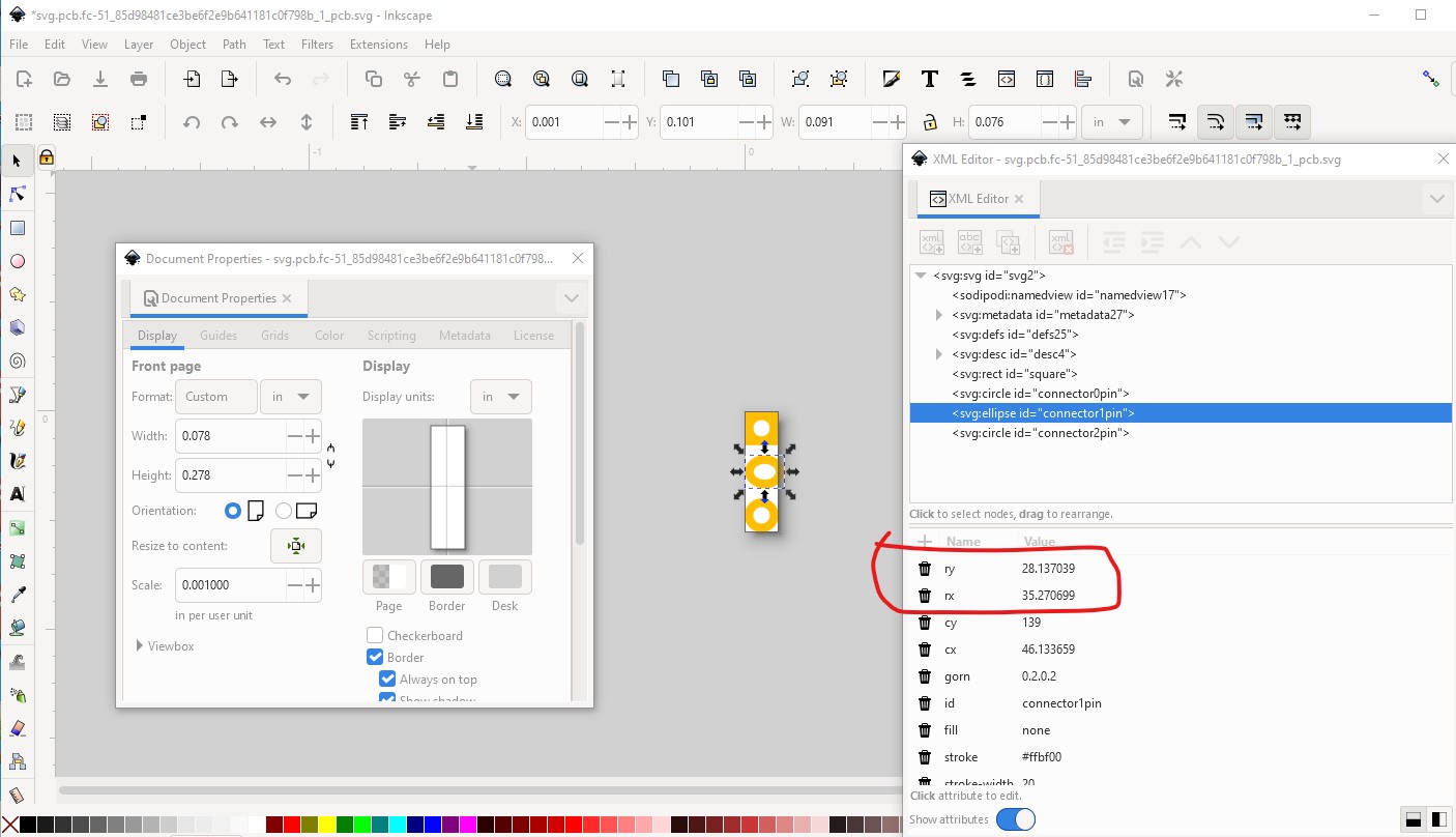
One unfortunate side effect of rescaling (due to floating point round off) is that circles in the original document will often become ellipses in the scaled document. As well as being wrong if the original element was a circle, in the pcb svg for connector pins, this becomes fatal as the gerber code will not create a hole in the pad if the pad is an ellipse. The only cure I know of for this is to manually change the radius of the element back to the original size via xml editor. A more efficient way (especially for a large number of elements) is to use global substituion in a text editor or write a python script (which I have not done yet) to do it automatically. In this case the original document has ellipses rather than circles so I converted one mounting hole before scaling from an ellipse to a circle:
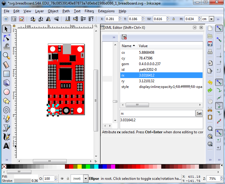
change it to a circle via xml editor by changing both rx and ry to 3.1(3.099999 after fp roundoff)
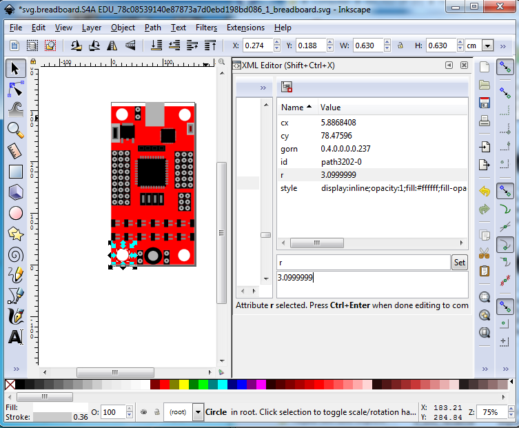
then rescale the document, which turns our circle in to an ellipse:
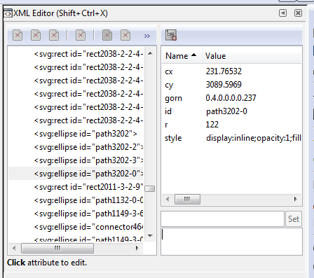
So do the same thing again, change rx and ry via xml editor to the same value and it turns back in to a circle.
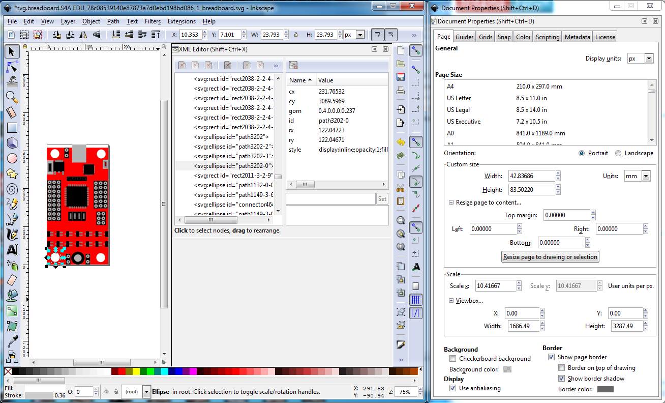
repeat for all the rest of the circles. For pads that have a square, or an oblong path (to make a non circular pad), they have an underlying circle to make the hole (that is the only way Fritzing will make the hole). The rescale may have altered the positions so you need to correct that if it has happened. To do that record the x y coords of the circle and its diameter from the tool bar. First change the w and h of the rectange or path to match those of the circle. Then change the x and y coords of the rectangle or path to be the same as the circle’s (we did w and h first, because changing them will change the x y coords too.) At this point you want to first fix up the view box in case the changes have modified it in a bad (to Fritzing) way. So do
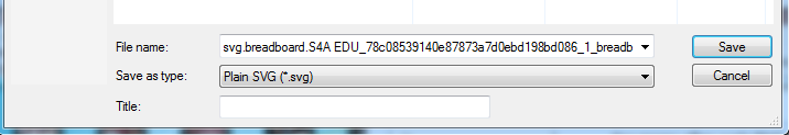
Now do Edit->select all and then Document Properties->Custom size->Resize page to content->Resize page to drawing or selection to reset the viewbox, then File->Save as type plain svg to save the resulting document in a Fritzing friendly format.
You now have a properly rescaled document and can continue on with making your part. Why it is desirable to rescale the document is somewhat of a mystery, although here are my reasons: it is called for in the parts file format. Unfortunately I wasn’t involved in Fritzing when the developers that wrote the parts file format document were still involved, so I don’t know their reasons but I assume they had them. From my point of view a known scale makes automated checking of the spacing in documents by the part checking script easier. The script doesn’t yet do so, but in future I hope it will. The script does declare an error which when the script becomes part of the parts submit tool chain will stop the part from being accepted. From a selfish standpoint it makes it easier to figure out and/or change the size of a hole in pcb view. For Inkscape, the hole diameter in pcb is size = pad diameter + (2 * stroke width). With the scale set to 10.41667 and the standard 20 thou ring size, a .1 header hole (which should be 0.038in hole diameter) is stroke-width 20 * 2 = 40 + desired hole size 0.038, making the pad diameter 0.078in. So setting the w and h of the pad circle to 0.078in will give you the correct radius of the circle (it will also move the circle in x and/or y) so record the radius value from xml editor, then use Edit->undo to back off your w and h changes and instead change the r field in xml editor to the new radius you recorded from xml editor. This increases the radius of the circle (referenced to the center of the circle) and thus does not change the x / y position of the circle (or more correctly changes x and y evenly around the center) maintaining the 0.1in pitch between pads. Laziness at work.
Edit 12 June 2023 Update:
Starting on an Inkscape version after 1.0.2-2 (2021) the procedure has changed. If you instead get a document properties screen which looks like this (this is Inkscape 1.2.2 (732a01da63, 2022-12-09))
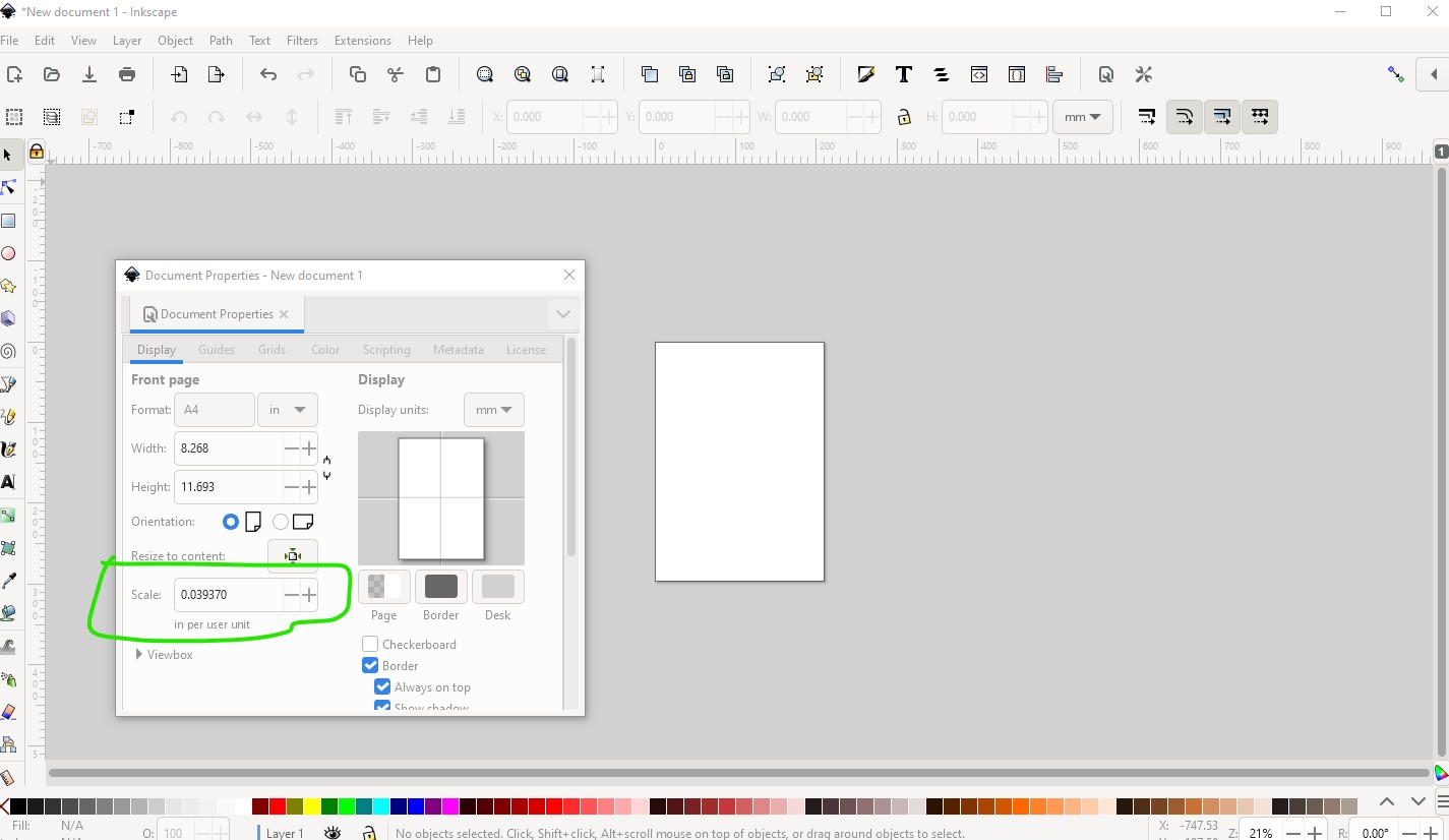
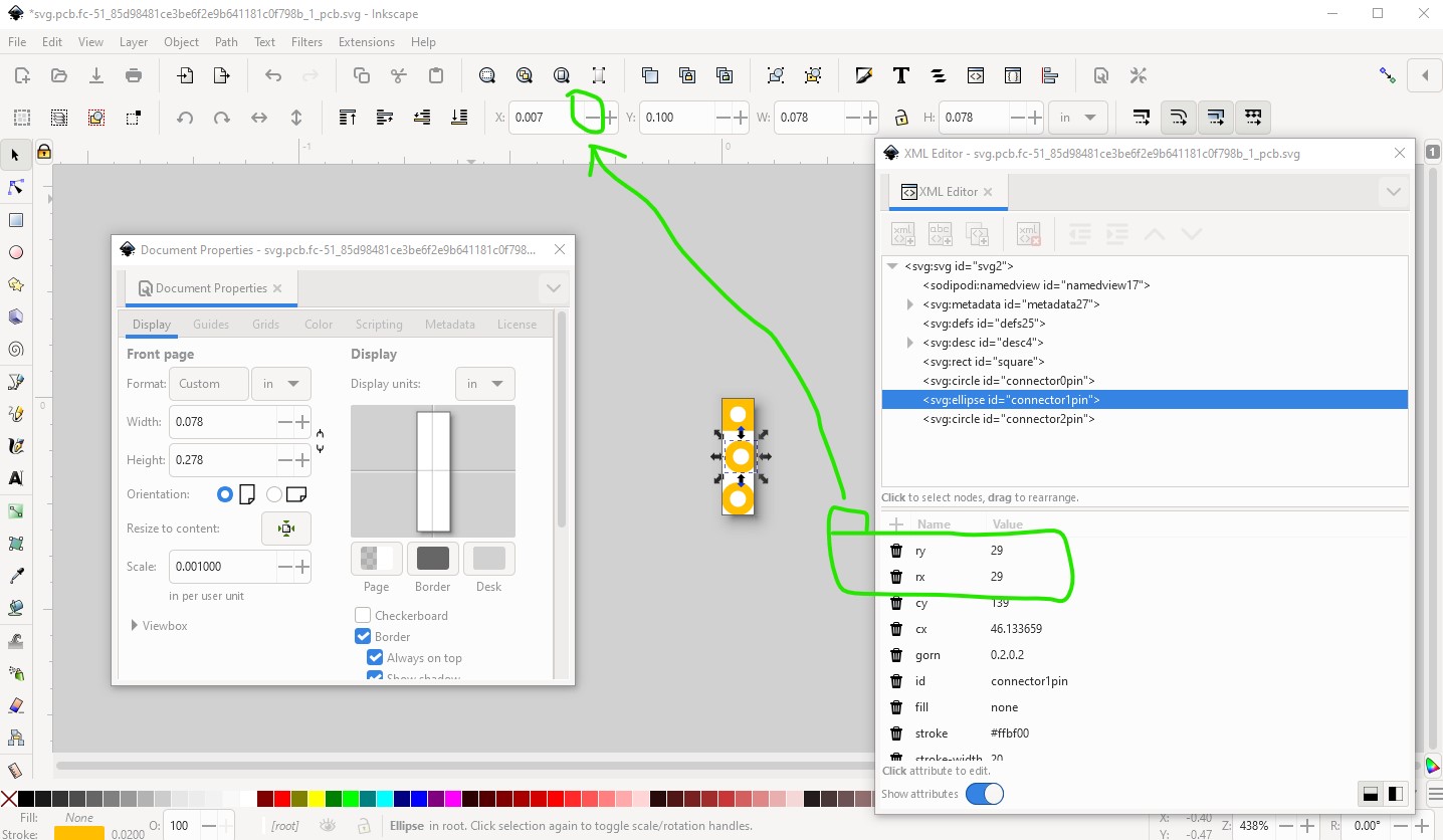
the scale parameter is no longer 10.41667, it is now in inches (if the dimension is inches) and needs to be 0.001 to set the scale Fritzing wants (for mm it needs to be 0.025400.) As well I have discovered a way to avoid floating point round off changing circles in to ellipses (which is a PITA!) Here is an example of the problem. I took a pcb svg and increased the scale to 1.0 from 0.001
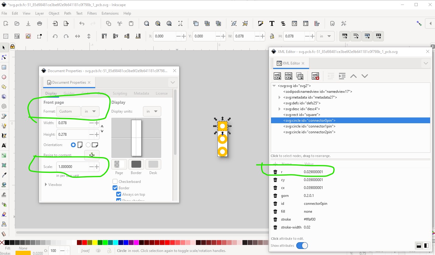
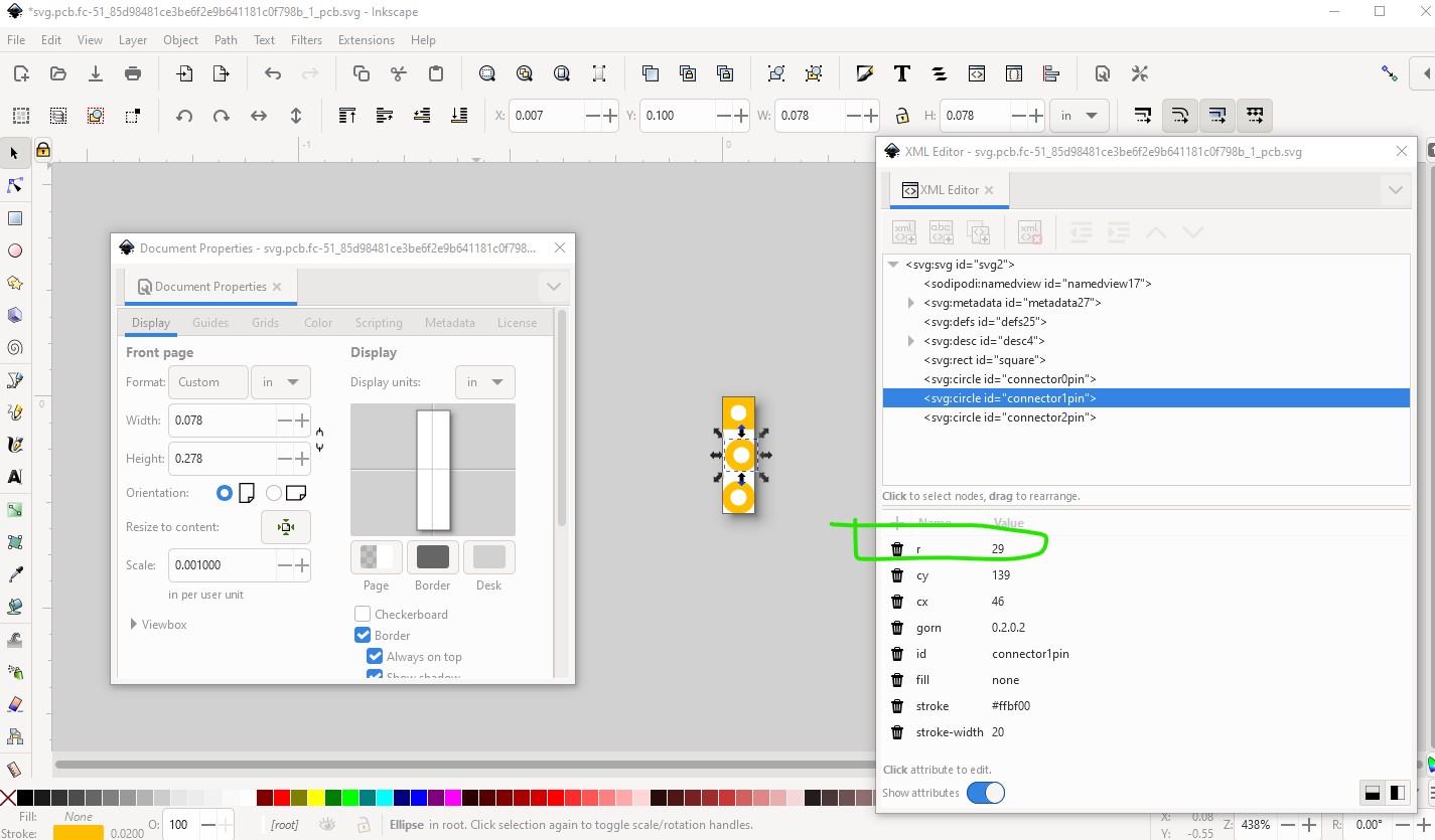
note the radius (r) is 29 as it should be for a 0.1in header. Now I rescale the svg to the desired 0.001 scale:
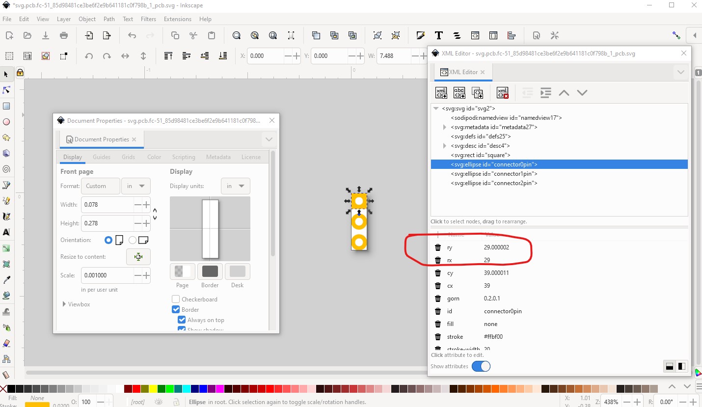
floating point roundoff has created an ellipse which will break gerber processing (no hole in the pad will be generated from this!) Then I went back to the original svg with the scale at 1 and did this instead. Here before doing the rescale I locked width to height in the toolbar like this:
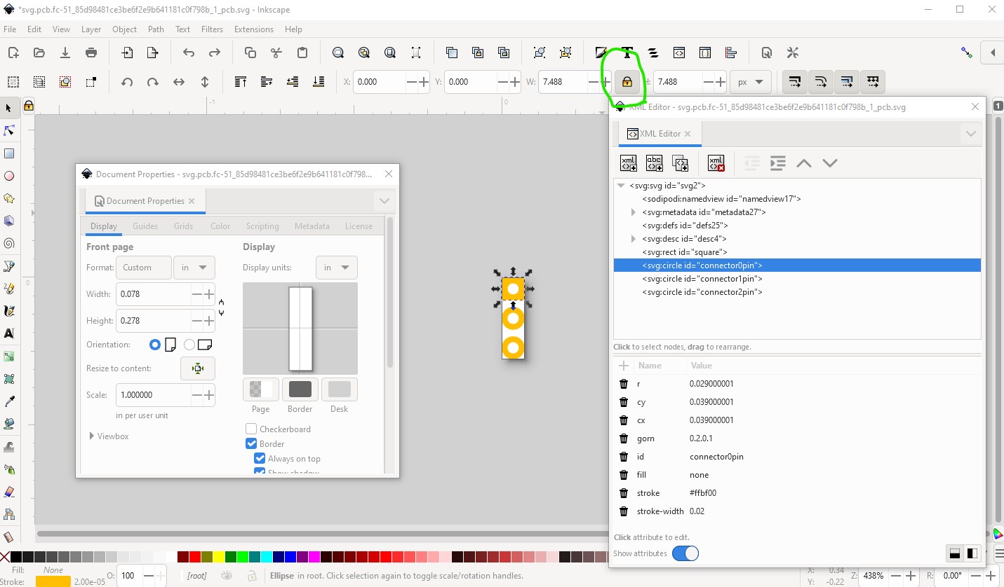
now when I rescale the svg the circle remains a circle (and has in all the times I have done this!)
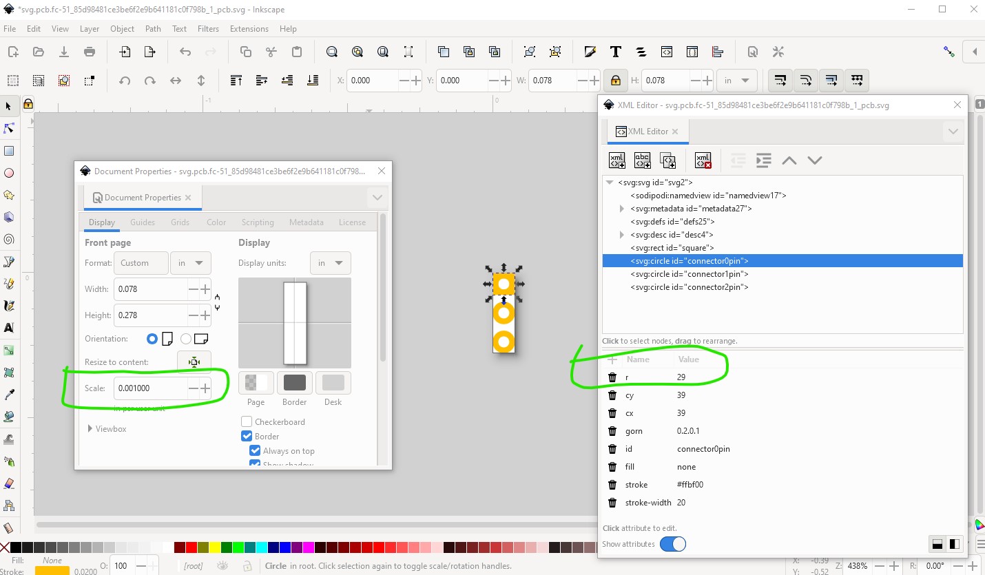
So do this when rescaling to avoid having to fix the circles. If you get an ellipse instead of a circle, to cure it set rx the same as ry and then use the tool bar to move the circle back and forth (so it will come back to the same place) like this:
first correct both rx and ry (note it does not create a circle from this!)
now click the - button on the tool bar to move the element in x (y will work as well) then move it back so it is in the same place it started. This causes Inkscape to change the ellipse to a circle as desired.
while this works, it needs to be done for every ellipse which is a major PITA!