Not much wrong. The breadboard svg is missing its layerId which will cause the part to not export as one of the image formats. Easy to correct, at the end of the svg edit, select all in all layers, group it and set the group name to the layerId (breadboard in this case.) The scale isn’t correct, so as this wants to be a core part I corrected it, (instructions here:
I initially added a 7 segment display set to 0.00 then realized you are likely going to use the text function to be able to set a value in a sketch for documenation purposes, and removed my addition as unneeded. The same thing done in schematic below will also work in breadboard. Moved the connectors to be exactly on .1in boundaries to line up with the .1in grid in breadboard (minor position change), in practice unnoticable.
schematic
start from schematic template which has the correct scale connector layout and line widths and colors. Available here:
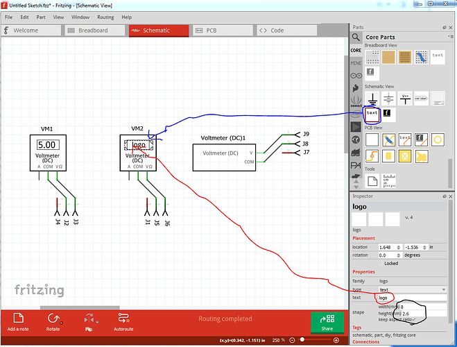
Added 1 pin to bottom row for the A pin so that schematic matches breadboard, but left it inhibited so it isn’t active in schematic. If you prefer to eliminate the A pin in schematic, just delete it again, either way is acceptable. This image indicates what I meant about adding a voltage value in a sketch (if as seems likely this part is being used to create documentation.) Here from the sketch I added a text field and set the “voltage” to 5.00. As you may know you can change the size with the width and height parameters in Inspector and change the text in the same place as shown here. This also works in breadboard (which is I assume why the display field was left blank.) In general it is desirable for parts in schematic to be as small as possible as room in schematic is limited
Rename the breadboard and schematic svg files to append an _1 i.e. svg.breadboard.multimeter_v_dc_breadboard_1.svg to make a new unique (and more standard) file name. Do the same to the fzp file part.multimeter_v_dc_1.fzp. This will allow this to be a new part that will load along side your current part. Delete icon and pcb svgs, breadboard will be reused as icon and pcb svgs.
fzp file
change the moduleId to multimeter_v_dc_1 (as it must be unique) correct the fritzing version to 0.9.4
change the label to VM (as the first 4 letters of this will become the label VM1, VM2 in this case (although I see it did not in fact truncate your labels, I thought it only did 4 characters …)
change property type to variant (I expect either will work, but variant is more standard)
delete the taxonomy as uneeded (and incorrect in this case!)
insert a trailing _1 (as a version number) before the last breadboard image name:
<layers image="breadboard/multimeter_v_dc_1_breadboard.svg">
replace the iconview and pcbview layer names with the above line. That will use breadboard for the icon and as the pcb view (which is effectively no pcb view as the layerIds won’t match)
remove the terminalId from breadboard, as they are not defined in the svg and thus aren’t needed (although while they won’t hurt anything if present, removal is more correct)
<p svgId="connector0pin" terminalId="connector0terminal" layer="breadboard"/>
to
<p svgId="connector0pin" layer="breadboard"/>
remove pcbview entirely as uneeded. Now either run the part file through FritzingCheckPart.py (which is what I did) which will check for a variety of errors and make some xml adjustments. If you don’t want to run FritzingCheckPart, you need to edit each svg file with a text editor and remove the trailing px from the font-size commands, i.e.
style="font-size:49px;font-family:'Droid Sans';text-anchor:middle;fill:#555555"
needs to become
style="font-size:49;font-family:'Droid Sans';text-anchor:middle;fill:#555555"
because in some circumstances Fritzing will change a font-size ending in px to 0 essentially deleting the text. The CSS standard requires the px in font-size and the svg editors obey CSS. Here is a new version of your part with these changes. If you unzip the fzpz file, you will get the fzp and 2 svgs which you can compare to your original files to see the changes.
multimeter-improved.fzpz (6.3 KB)
Peter
