Pins not aligning with board

I’m trying to create a component (a large, obsolete 7-seg display).
It has two rows of 5 pins that in the real world line up on veroboard with rows 1 and 20.
In Inkscape, I’ve placed the pins using a grid of 0.1in (and sanp to grid), and with 1.9" between the two rows of pins.
When I bring the SVG into Fritzing, the pins line up with rows 1 and 21.

I’m sure I’m missing something obvious, but can anyone suggest why this is happening?

If you upload the part file (In parts editor you need to Save as a new part, which stores it in the mine parts bin, then right click on the part in the mine parts bin and select export part which will write it as a .fzpz file) I’ll have a look at it and tell you what is wrong. Upload is 7th icon from the left on the reply menu.

Peter

What you described looks correct. What editor are you using to manipulate the SVG file? An off by one error like that sounds strange, but an error in the svg height and width values and units could give that effect. As @vanepp said, a copy of the part gives more to work from. If the import into Fritzing happens to be where the problem starts, then a separate copy of the svg file would help too.

I see in the existing parts library, a 7 segment display with (a very odd) 2.36 inch (6.01 cm) row spacing. Not close enough to be very useful directly.

Thanks for the help.
Hopefully these uploads work …
7 Segment Display ELS-1806.fzpz (16.9 KB)
7segment_1,8in_ELS1806

The breadboard image svg file did not have any units specified for the width and height. Just raw numbers without units, which defaults to px. Frtizing tries to convert that, but does not always get it right. I do not use Adobe Illustrator, which this was created with, so I do not have handy the details on how to fix it from there. I have seen references to tutorials that provide the instructions though.

<svg xmlns="http://www.w3.org/2000/svg" x="0px" height="211.65355" version="1.1"  width="143.62204" viewBox="0 0 143.62204 211.65355" gorn="0" xmlns:xml="http://www.w3.org/XML/1998/namespace" id="Ebene_1" xml:space="preserve" y="0px" enable-background="new 0 0 138 200">

I fixed it just using a text editor. Changing that element to

<svg xmlns="http://www.w3.org/2000/svg" x="0px" height="2.1165355in" version="1.1"  width="1.4362204in" viewBox="0 0 143.62204 211.65355" gorn="0" xmlns:xml="http://www.w3.org/XML/1998/namespace" id="Ebene_1" xml:space="preserve" y="0px" enable-background="new 0 0 138 200">

And recreating the part file seems to have fixed it. As my initial guess pointed to, the problem was the height and width units.

7 Segment Display ELS-1806.fzpz (17.2 KB)

svg.breadboard.7 Segment Display ELS-1806 (CA)_6593fa4ad7ff2a8d4dc90fc631df8a31_2_breadboard|1x2a

Awesome, problem solved.
I started from a stock svg and edited that in Inkscape. I guess the original was created in Illustrator. I have little experience of either so a good lesson to have learned.
Thanks very much.

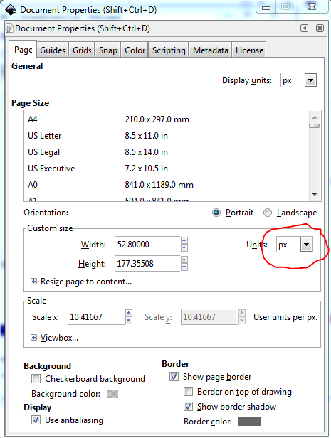
In Inkscape this is usually fairly easy. As long as the scale is correct, File->Document Properties will easily change the view box dimensions. Your original will have looked like this (this is Inkscape 0.9.4):

changing that field to this,

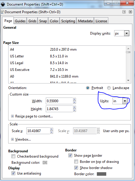
and doing a File->Save as and selecting Plain SVG as the Save as type values will update the svg. The exciting times come when the scale is wrong (early Illustrator used 72 DPI, Inkscape to 0.9.1 I think used 90DPI and 0.9.2 and later use 96DPI as px values. If the scale isn’t correct you need to rescale the document (and I think that needs Inkscape 0.9.3 or later, as the scale wasn’t in previous versions I don’t think.) There is a howto here on rescaling using Inkscape:

These two may be useful as well

Peter

Thanks
I’m having another problem with the same part.

When I place it on a board, pins 3 and 8 seem to be joined together. I presume this is something to do with a standard pinout for 7 segs using these pins for a common anode and the fact that I’ve used a 7-seg .fzpz file as a starting point.
The (obsolete) displays I have have a different pinout, with 1 and 5 as the common anode.

I’ve tried everything I can think of - starting with new SVGs, checking and resasigning the connections and pins in the Fritzing parts editor, I’ve checked the breadboard, schematic and PCB views, but I can’t see anything that would cause this.
Any help would be gratefully received.

It sounds like the original part has a couple of pins bused (which will cause them to connect together internally). Yes, from the .fzp file of your part above (found by unzipping 7 Segment Display ELS-1806.fzpz above), pins 3 and 8 are bused together as the anodes:

<buses>
  <bus id="anode">
     <nodeMember connectorId="connector3"/>   
     <nodeMember connectorId="connector8"/>
   </bus>
</buses> 

You likely want to change the connectors above to connector1 and connector5 to match the

  <connector name="common anode" type="male" id="connector1">
  <description>common anode</description>
   ...

and

  <connector name="common anode" type="male" id="connector5">
  <description>common anode</description>

connector definitions further up the .fzp file. The bus connectors need to match the id field in the above. It is probably easiest to use a text editor to make the change, I know parts editor can set buses (they are called internal connections in PE), but I don’t know how you delete existing connections in Parts editor although there may be a way. If you use a text editor to make the change, you can then rezip the .fzp and the 4 svg file in to a .fzpz file and the part should work when the .fzpz is loaded.

Peter

Thanks Peter
I’m struggling to find a way to extract the .fzp from the .fzpz
Any tips?

Any zip program should work I use 7zip (open source and all platforms I think). The fzpz is just a zip file at worst you can change the fzpz to .zip and the normal zip program should work if it objects to the .fzpz (7zip doesn’t care.)

Peter

1 Like