Making parts is complex enough that not many do it. It is to our advantage to encourage people to make parts (over and above, tearing people a new one just seems rude ![]() .) The folks that trained me (sadly no longer posting) were happy to answer questions so I’m carrying on the tradition.
.) The folks that trained me (sadly no longer posting) were happy to answer questions so I’m carrying on the tradition.
True the part is functional, the errors are mostly cosmetic. These two tutorials on part making cover the current version of Fritzing (most of the rest are for older versions):
At a guess, you edited the schematic file in Illustrator. The original from Adafruit is correct (dimensioned in inches), your version is dimensioned in px at 72DPI which is why the scale problems. This is typical of Illustrator and if it is possible to convince Illustrator to use inches I don’t know how (from google searches I think it may not be possible, but if someone knows how please post!)
In any case here is how to convert the svg to something Fritzing will scale correctly using Inkscape (which is my svg editor of choice): the problem is the svg is dimensioned in px and Illustrator uses 72DPI as the px value. Inkscape used to use 90DPI and now uses 96DPI (the current CSS standard I think.) Fritzing tries to guess which DPI was used and sometimes as in this case gets it wrong. Here is the original document displayed in Inkscape:

Then the SDA pin with coords in inches:
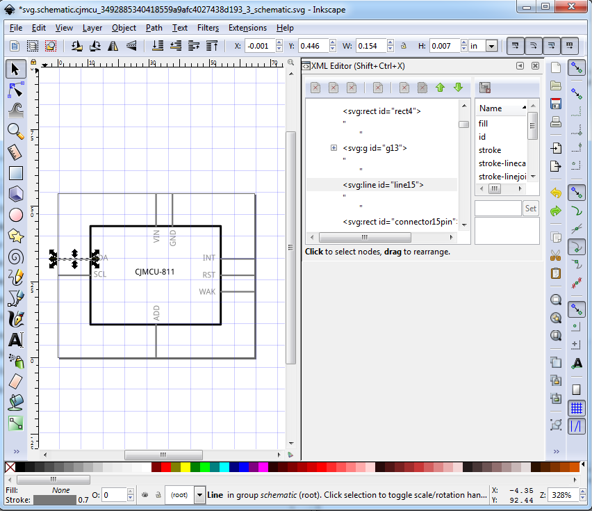
Note the Y cood is 0.446in in the top tool bar. Then the SCL pin below it also in inches:
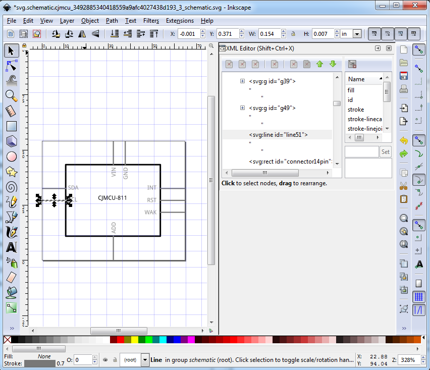
Note this y coord is 0.371in (not the 0.346in it should be to be on .1in centers.) To fix this, I first ungrouped the svg:
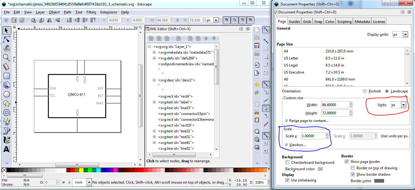
and recorded the scale (1.00000, circled in blue) for later. Note the Units (circled in red) are in px. Now make sure Scale stroke-widths (circled in blue) is enabled, and change Display Units (circled in red) to pt (points or 72DPI) to match Illustrators opinion of the DPI value. The scale (also circled in red) has changed to reflect 72DPI.

Now change the scale back to 1.000000

Note the image has gotten larger as it is rescaled. Now change the Display units back to px and the Units to inches (so we don’t have this problem again, because an inch is always an inch unlike the DPI values.)
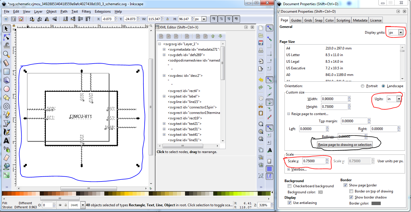
Now we need to click Resize page to drawing to reset the viewbox to the correct coordinates but at an incorrect but consistent (i.e inches not DPI) scale.
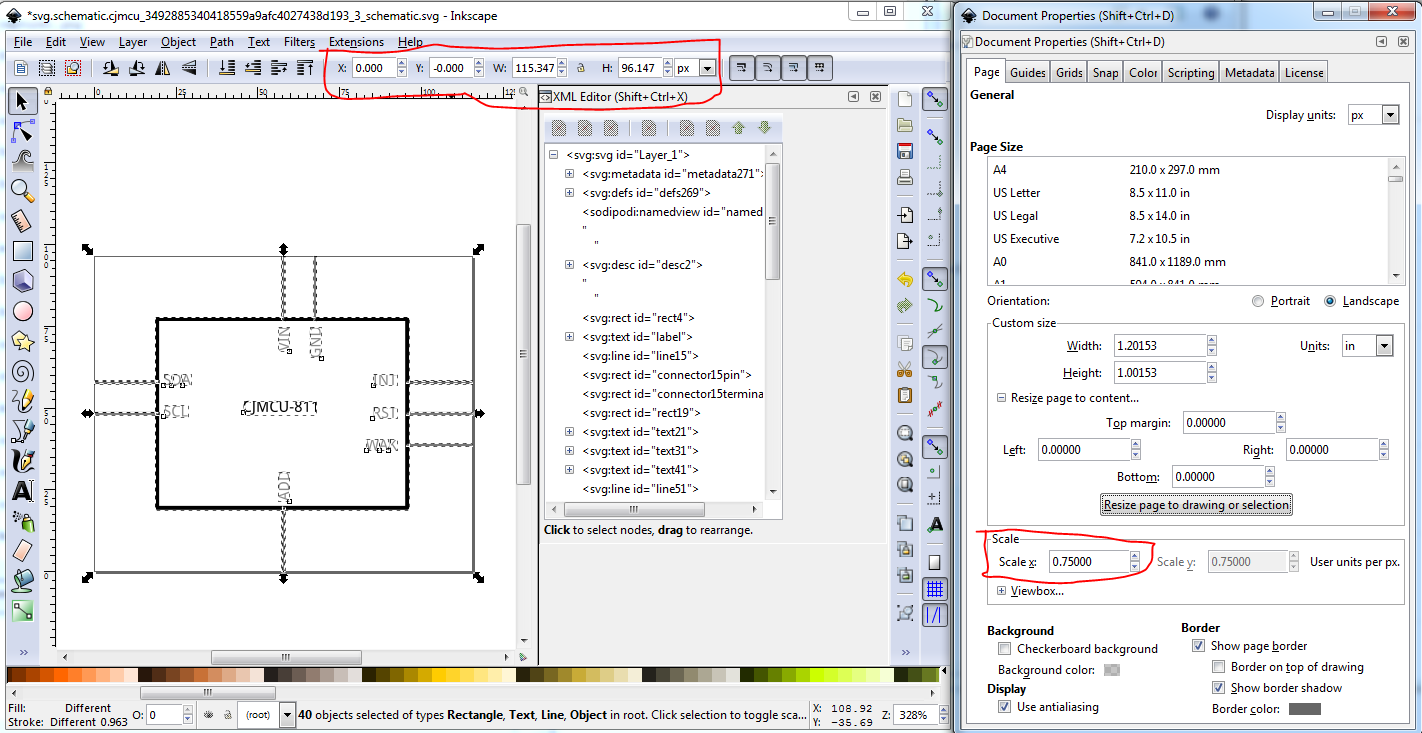
The scale here is 0.75 but the parts file format calls for the scale to be 10.41667, so we should (but I am too lazy to do so right now ![]() ) these instructions to reset the scale:
) these instructions to reset the scale:
As noted if it is possible to get Illustrator to do this for itself, instructions on how to do it would be much appreciated. The discussion I’ve found seems to indicate Illustrator won’t let the user adjust the viewbox settings and I assume also the scale (although I would like to be wrong ![]() .)
.)
Sure I should be able to do that. I’m github challenged, I can get the first pull request to the main parts repo to work, but after that I have yet to figure out how to keep my cloned repo in sync (although I have some suggestions I haven’t tried yet.) but a one of I should be able to do.
Peter