I’ve been attempting to clean up some of the previously submitted audio parts from Synth-DIY multi-part bin
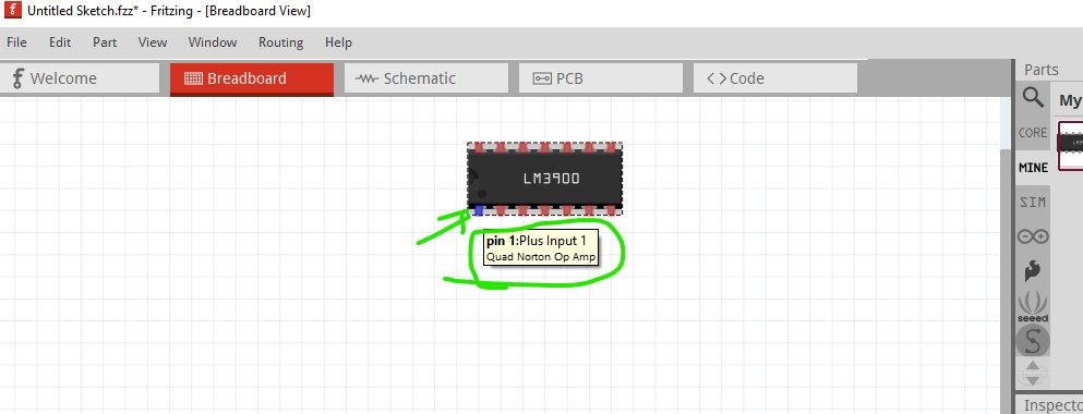
The LM3900 lacked pin labels (in some views) and the actual schematic was not displaying. So I unpacked it, ran into an error with a subpart in the fzp, removed that and ran it through check parts. packed it back up. no joy.
Maybe someone can see how to fix this part: LM3900.fzpz (6.5 KB)
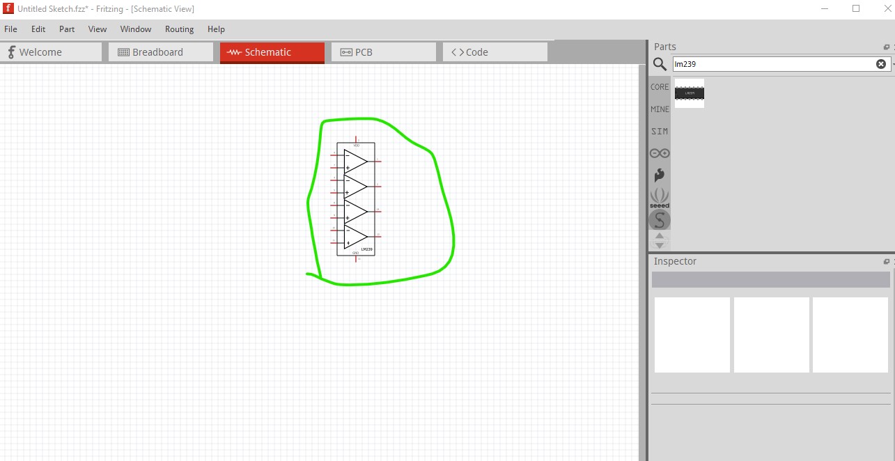
There is already a corrected multipart lm339 in core parts from 2019 (probably by request of the original poster, as I rarely submit to core parts from this post:
Better to use that one. Your part above is a generic IC not a multipart part which will have a number of problems.
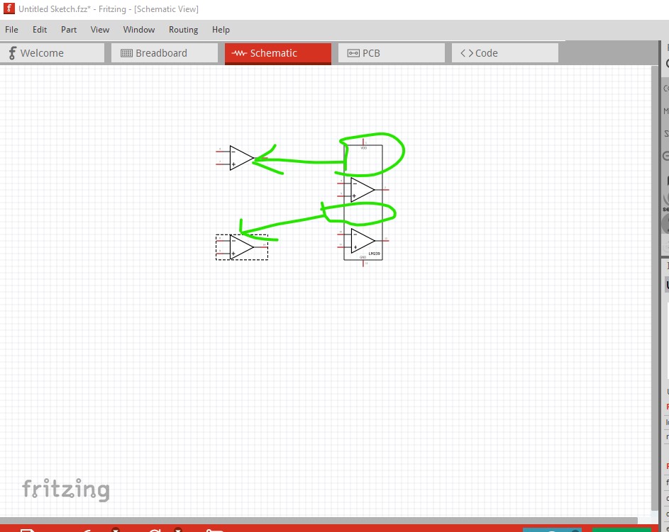
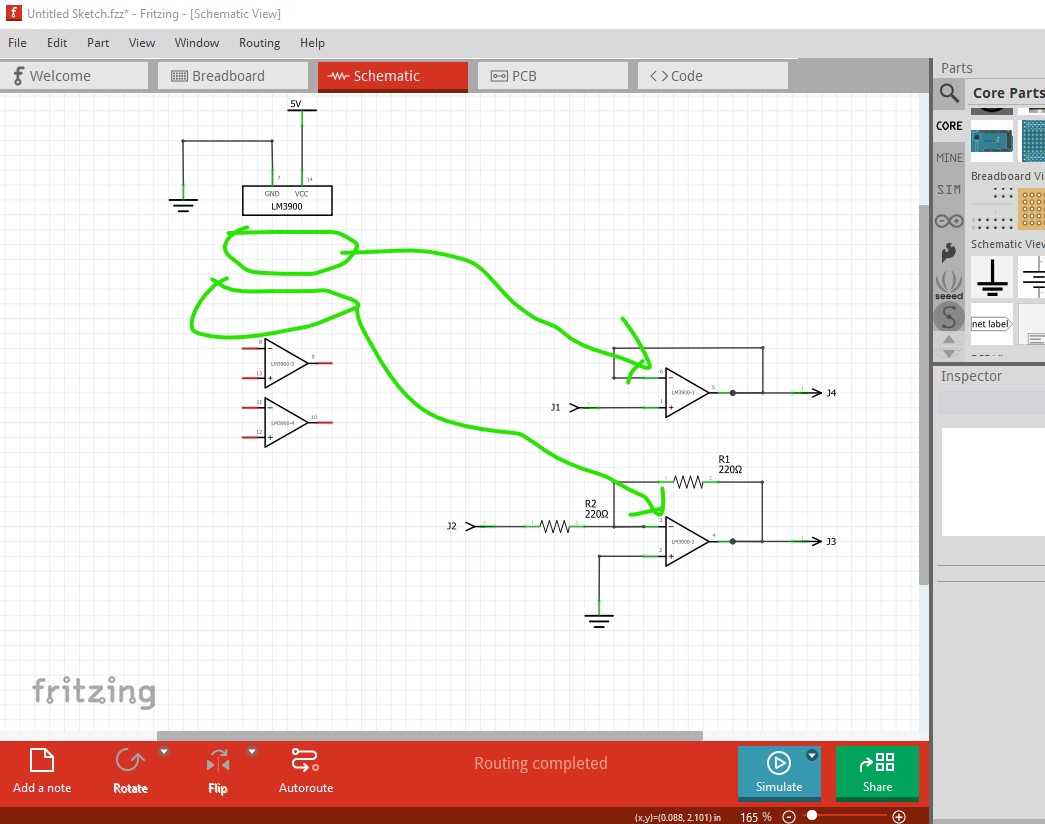
The advantage of subparts in schematic with multi op amps (as in this case) is being able to move individual elements around like this. It is a lot more complex to configure but for multiple op amps in particular worthwhile learning.
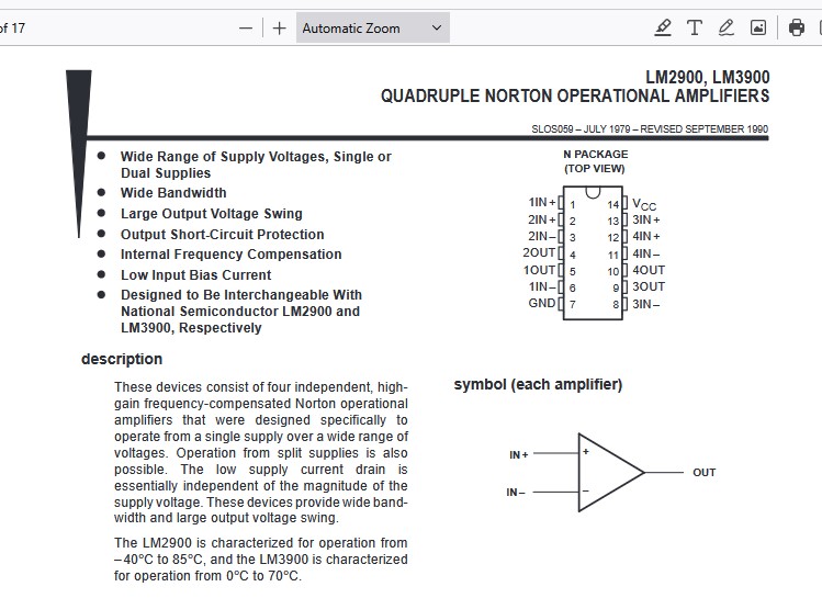
In the quoted article, the reference is to a LM 329. Neither of those are the LM3900. The LM3900 is a quad Norton op-amp, which is not a a comparator. The latter is voltage the former is current driven. Very differnt beasts.
EDIT: please note that the tiny svg in my first post reflects the correct original layout using subparts which I believe is the reason the svg doesn’t work. I just don’t get how the original subparts thing worked.
My bad, got the wrong part on a search. Your svg also doesn’t have subpart definitions in it (they need to be in the fzp file as well and they aren’t there either.) I’ll modify the LM329 part to be a LM3900. For a subpart part you need the 4 op amp images to be defined in the svg, a generic IC won’t work.
The part I uploaded I had had to remove the subpart definitions from the part file to get through part checks.
I don’t need the subparts, per se, it’s just that the svg of the schematic view is completely ignored. Looking at the svg, it seems to have pins and terminals defined correctly. I don’t get why it isn’t used. I don’t need a view with op amp stages as in the TL074 from that same collection. For schematics it is ‘the usual’ way op amp stages are depicted, but, it’s not a must for my part.
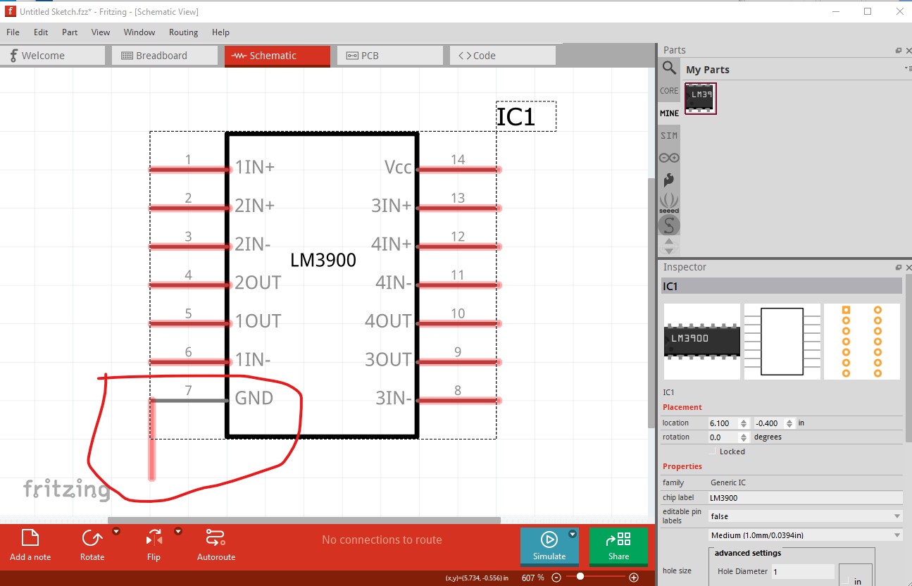
Sorry I was misunderstanding what you were asking. Your problem looks to be that you left the family at Generic IC. with that, the loader considers the part to belong to the parts factory and something (likely the variant I expect) is causing the wrong schematic svg to load. This is your original .fzpz, schematic is wrong.
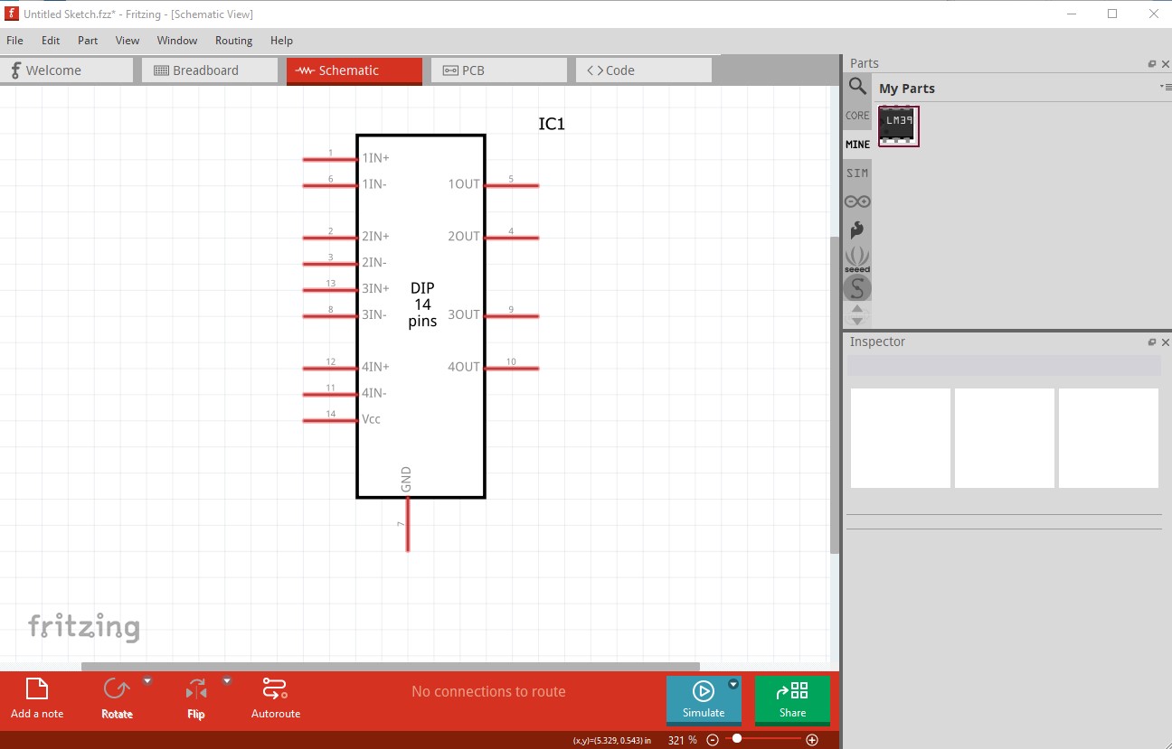
where the family is no longer Generic IC and now the part works as expected. It is always a good bet to change the family when making custom part with the generic IC as the loader will associate the file with the parts factor if the family is Generic IC and the pull down menu will change to other family members. In this case I expect there is another variant 12 with a different schematic svg and that gets loaded (likely the entire part) which isn’t what you want. That change produces this
In the mean time I will make a subpart version of the LM3900 and you can see if you like that better (it is more useful as you can split the various op amps up.)
Here is a subpart part for the 3900. Feel free to use it if you like it.
edit:
Modify the pin labels to match the data sheet. To load this new part you will need to delete the old part in your mine parts bin then shutdown Fritzing answering yes to the save the parts prompt and the save the part bin prompt but no to save the sketch, then restart Fritzing (which will really delete the part) then load the new part below.
Sigh, so I swapped this in. There are no pin labels in the PCB view. I’ve edited them in with the editor. EDIT: I had labeled as per the Specifications from norton/ti. So, 1IN+, 1IN- and so on.
EDIT: I’m not sure I understand the subpart for the schematic view. The TL074 with subparts from the same collection, https://forum.fritzing.org/uploads/short-url/aVUakoLopB1aEEcxCFzBMlUG56b.fzpz makes sense. This view with subparts makes less sense. I mean from the vantage point of structuring a schematic diagram.
moving individual op amps in the quad to where ever in the schematic you need them. A fixed part (as you are using it in your diagram) doesn’t have that flexibility. The power block is movable as well and typically will be by the power supply with associated power bypass caps. Clicking on any op amp will move it anywhere in schematic not affecting any of the others in the quad unlike a normal part where everything moves. This is why multis are worth the effort of making them. Same applies to multi part logic ICs for the same reason you can put individual gates whereever you need them.
But, that is exactly what my image shows. The TL074 works, with sub-parts to allow you to use individual op amps as seen on the right. But the subparts version of the LM3900 that you uploaded does not. That’s what I meant with I didn’t get the point of the subpart (the lm3900 subpart).
I didn’t mean for it to get this complicated
Oh, strange. I removed that (I had already replaced it with the first one) removed the imports, restarted fritzing, re-imported the multi and now it works. Sigh. Initially, I could not drag the subparts.
I’m really frustrated now, since I can’t edit the part labels without, again (3rd time) re-routing. Please, let’s use the pin labels that are in the data sheets. EDIT: The reason it’s frustrating is that if you edit in the parts editor having selected the part but NOT in the sketch, you end up with a new part. That happened to me twice. It’s been a long day.
Unfortunately subparts are always complex . Just to be sure I understand, you are asking for the pin description in the fzp file to match the data sheet
or am I missing something again? For me this is an easy change (as I long ago abandoned parts editor for editing the files directly) so it is only a bit of editing and build a part.
Since discovering the Audio parts posted here, I’ve been happily using them But I’m not even able to edit simple schematic svgs
Yes, using the pin labels common to the datasheets helps a lot when glancing up and down from bread board, to datasheet, to fritzing and back. It really slows me down if I have to parse a description instead of recognizing the one on the sheet.
It’d be a great change, though I’ve done it by hand in the editor with the part selected from the breadboard, since the layout is complex and almost done.
I began editing the schematic which you corrected, but it looked fine The issue lay elsewhere which is where you come in
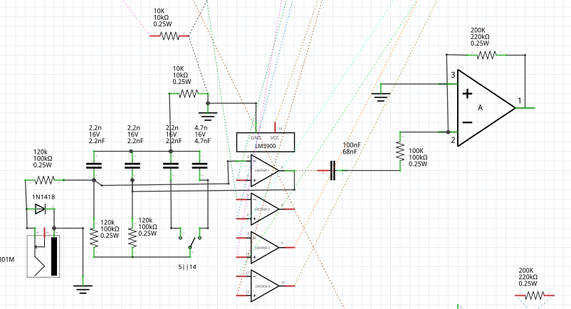
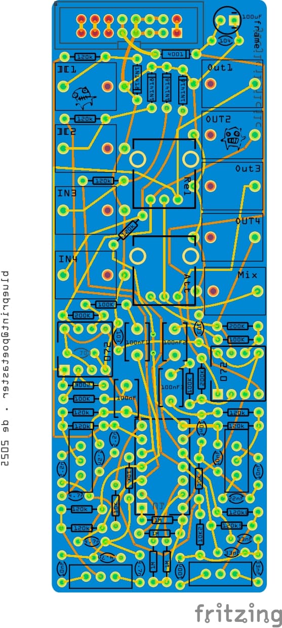
Thank you! It’s a part I will be using often. This is the first thing… an analog drum machine based on the gamelan resonator (from the work the pygmy gamelan https://pauldemarinis.org/Circuits.html) … this for eurorack. it’s difficult to do such a tight layout with tht parts, but, it looks like it might work…
OK, I have replaced the original part with a new one with the corrected chip labels. If you haven’t seen it (it gets posted a lot so you may have seen it already) this tutorial details how I make parts (without parts editor!)
there is an Inkscape extension in there that makes making schematic much easier as well as @RAPTOR7762 said a chapter on making schematic subpart parts.