I thought I was in the green on this one. I swapped the multi you created in (edited the pin labels) and produced some boards.
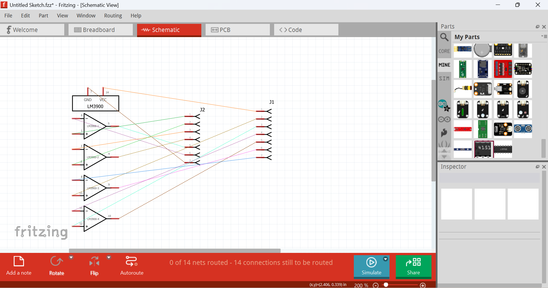
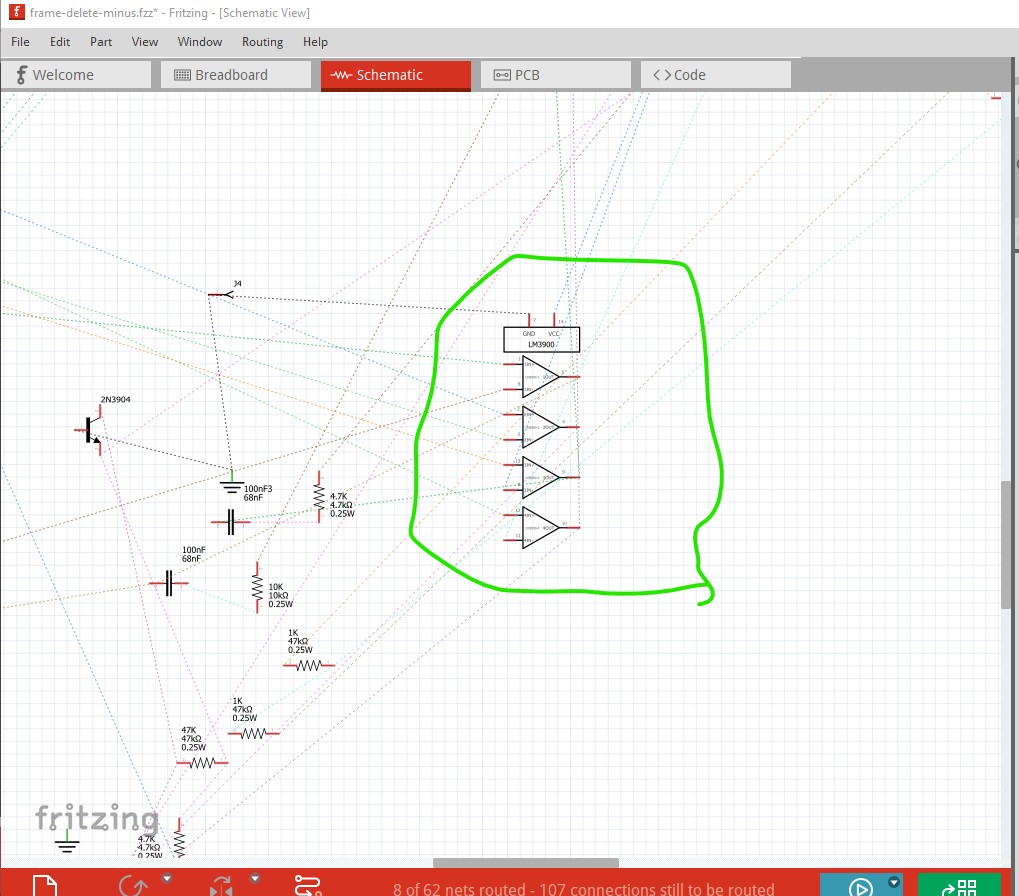
Then, I went to (i always do schematic cleanup last since it’s the most time consuming) and realized that the part in schematics view has no connections to any parts!
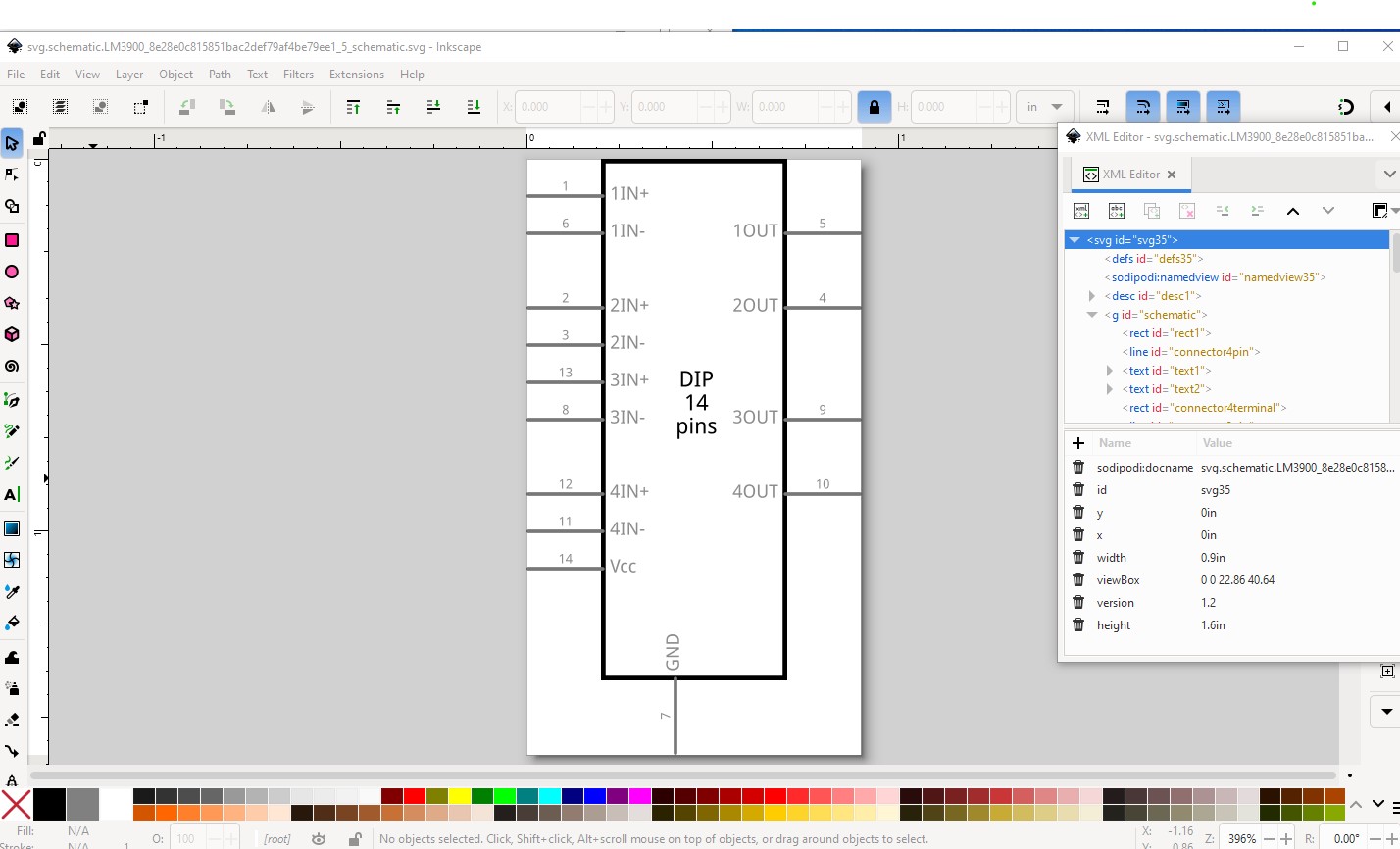
You would need to edit that part correctly to get a schematic subpart part if that is what you want to use. Your modification is incorrect which is what is breaking schematic. The schematic in your modified part looks like this:
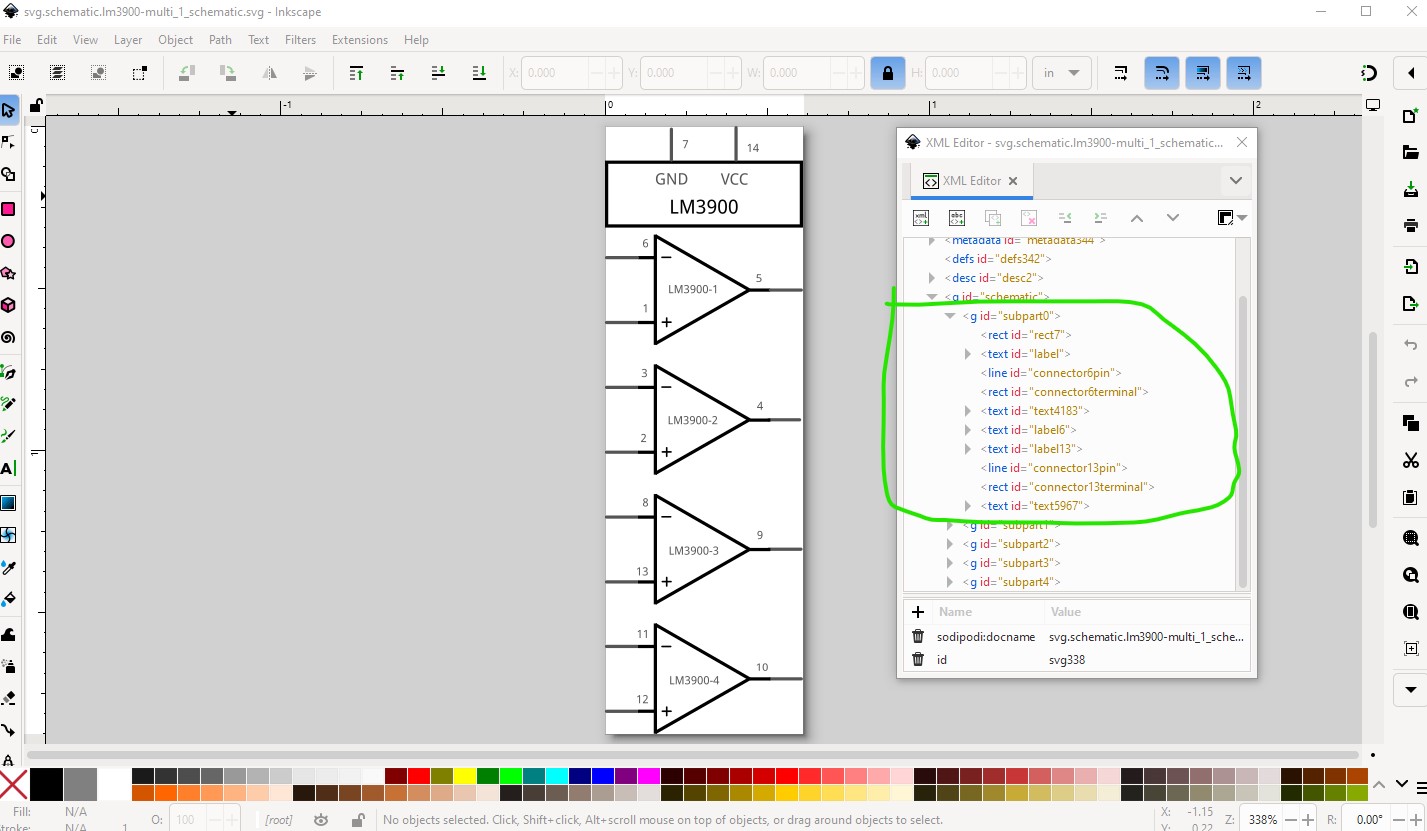
(which doesn’t match what schematic is showing and I don’t know why or how you managed to get this sketch nor how it is working as far as it is!) It needs to look like this to work. With the subgroups missing schematic won’t work correctly. You would need to add the text to this svg. That may which be difficult and may need changes in part size to make the op amps larger to get enough space to add the text. I can do that for you if you like and make sure the result works correctly.
The schematic in your sketch is operating as if the subparts are correctly defined, but I don’t understand how, as the exported part from the temp bin is incorrect and the subparts should be broken.
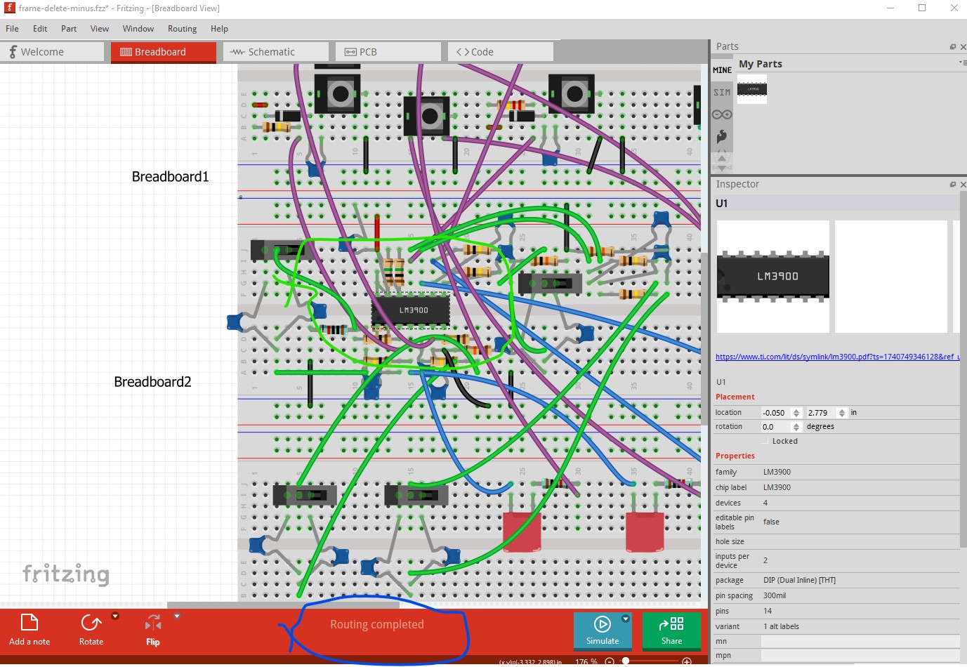
I really don’t know what happened here, but I’ve just started by removing that version and replacing it with your multiple again. That seems fine. I have to redo the traces, but, the schematic version seems fine.
Was really odd. After I removed the part (in breadboard view) it was also removed in the pcb view. But the schematic bit remained! Sort of a ghost part!
I DID use peter’s part. But something went south. In any case, I saved a new version and the same part works fine (ok, the labels not). I just have to redo all the routing.
EDIT: the only changes I had made after importing the lm3900-multiple part was to edit the labels and ‘save’. Maybe a bug in the parts editor? I didn’t modify anything else or open the file except to import it.
It is very possible. The parts editor (AFAIK) doesn’t support schematic subparts and thus may break things when saving the part. The result was certainly very strange, the subpart schematic was still somewhere but did not export with the part. As to the traces, if you delete the part with delete minus (as opposed to delete) it will delete the part but not the traces. You then add the new part and reconnect the traces (unfortunately manually in all views) by dragging the traces to make the connections again. It is often a PITA, and is sometimes (especially on pins with multiple connections) to just delete the wire and re route it but it does work. Would you like me to modify schematic to add your labels?
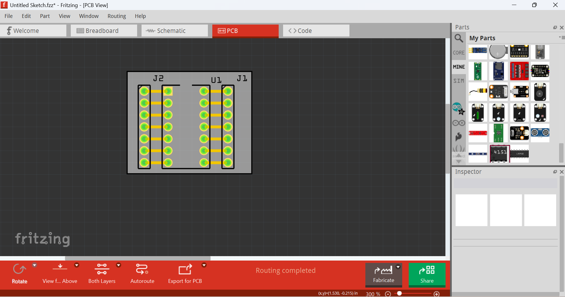
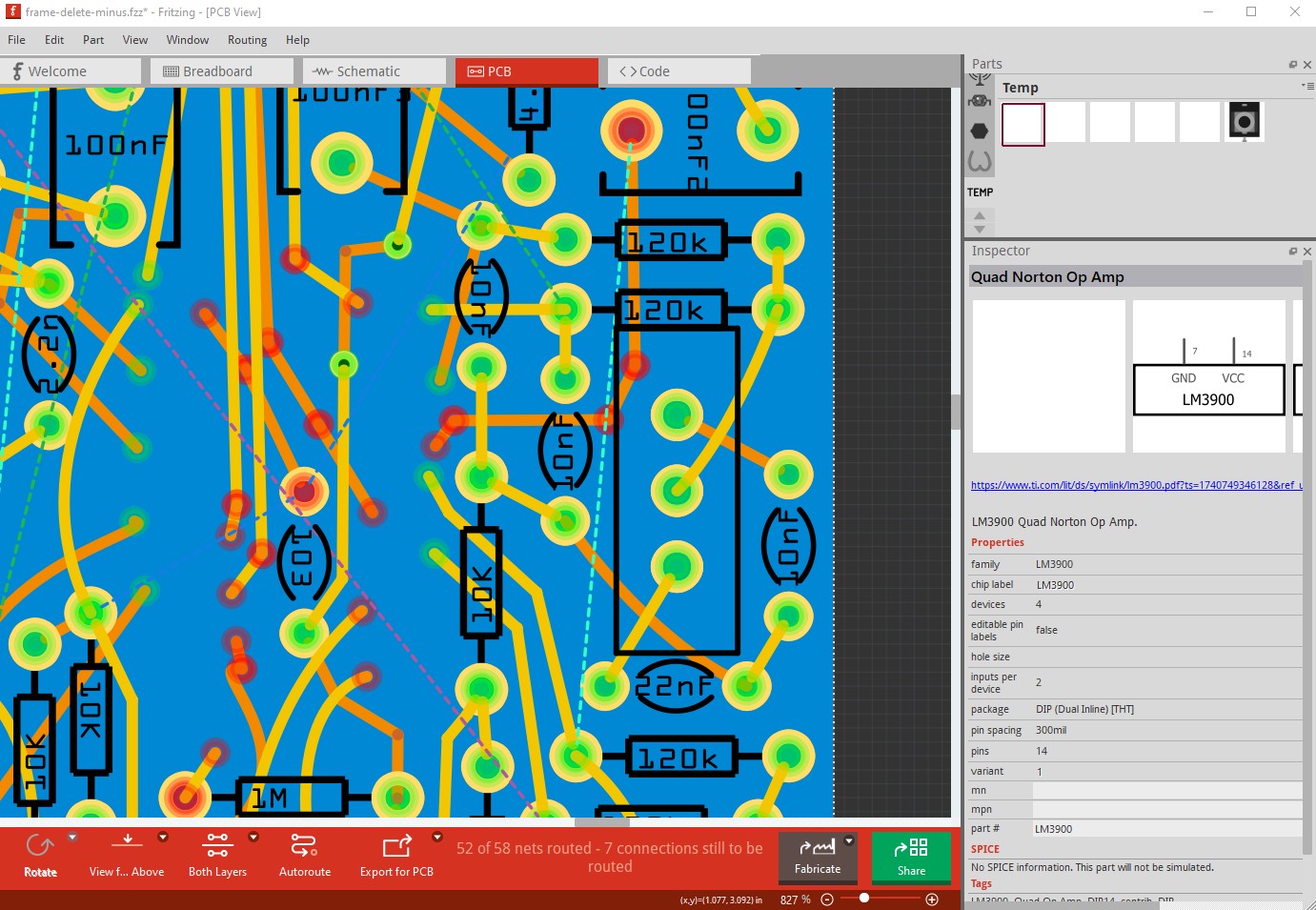
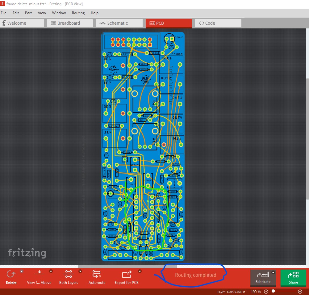
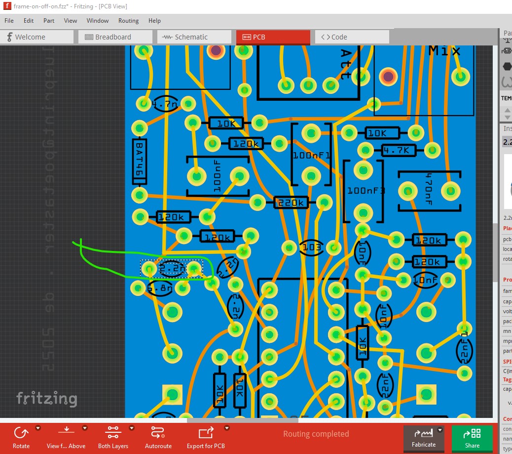
Unfortunately the sketch is fatally compromised. I did a new part and attempted to merge it in to the sketch but when saved the new part is missing (indicating the things I did to modify the sketch didn’t work. This is your original sketch where I did a delete minus on the lm3900 part (which you can see disappeared from pcb in this image) although it is still showing in the temp parts bin.
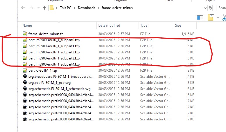
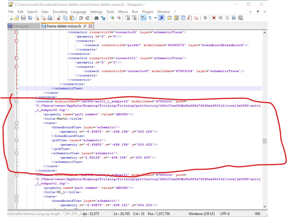
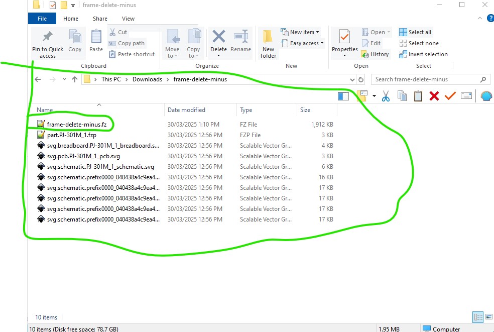
I then saved the sketch (which should have deleted the part from the temp parts bin. Unfortunately it does not. I unzipped the .fzz file and the lm3900 part is still present. So I removed it and rezipped the .fzz file
The only solution I know is to recreate the original sketch from scratch using this new lm3900 part (which has your requested labels) it doesn’t appear the current sketch is recoverable.
I would guess that the edit with parts editor fatally corrupted the sketch in a non recoverable manner (or there is something I just missed deleting in the .fz file either is possible!)
Oh, dear. I 've already redone the work with a ‘save as’ version, just deleing the lm part by hand and redoing all the traces from scratch. It ‘seems’ ok. I’ll produce some gerbers and check. In any case, it appears to be the ‘post edit’ version with my labels, but behaving as expected.
From my half-year experience of Fritzing part-making, I would like to share something — for simple parts, use the part editor. If you are making more complex parts, use the part editor first as a base, then edit FZP and SVG files. However as for me, my zip archiver has been giving problems.
As Peter mentioned, editing a part with schematic sub parts using new part editor breaks it, so sometimes it’s good to know how to edit FZP files
Of course, using the new part editor is much easier, as it’s “semi-automated”
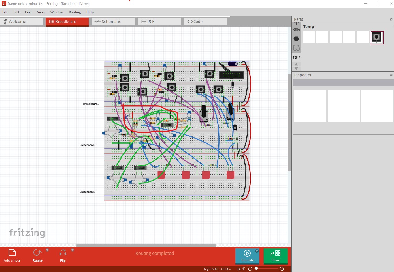
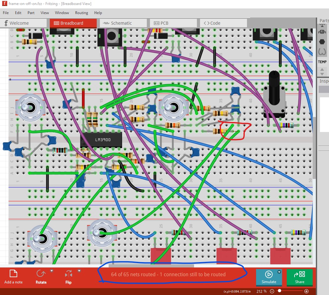
One potential problem (although pcb looks OK) there is a non routed net in breadboard that looks to be shorting a capacitor. It would probably be a good bet to verify this is OK before ordering boards.
I was going to suggest deleting all traces and redoing the wiring from a saved copy of the sketch may fix the issue (it may also be required to edit the .fz file though as sometimes it can’t delete connections because it has lost them!) Starting from scratch is the safest bet however.
I have, with @vanepp help edited parts (old pots for new) out of fzp files, so I can get around the XML. But it’s the inkscape work which get’s me everytime.
Well, it’s actually something completely unrelated. This rework has a fundamental flaw, but that’s all on me I can fix it, but this round was wasting time
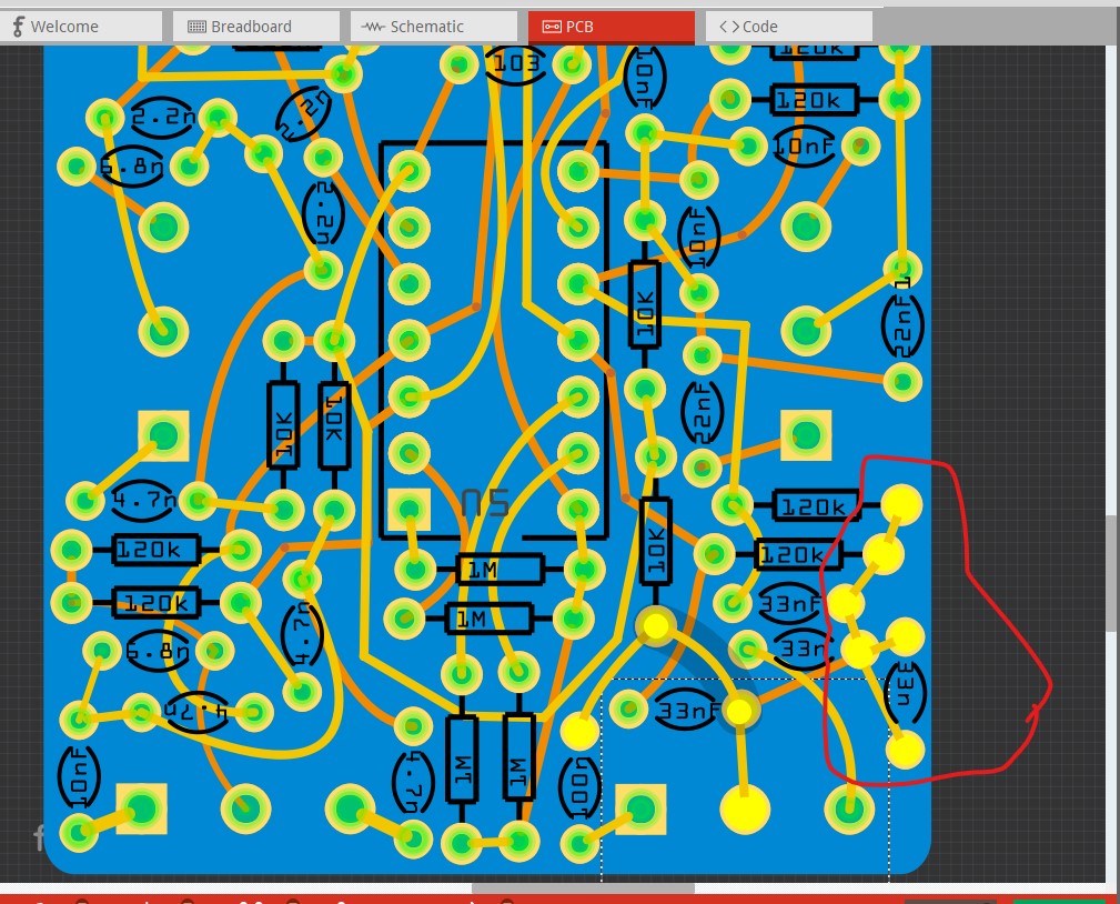
While I agree pcb looks correct, I would figure out why breadboard is showing a short between the two wires in breadboard. That will reflect in to pcb view and may be causing an error in pcb that you haven’t seen yet. Routing schematic would be a good idea too as that should show up the missing connection as well. There is in fact an error in pcb. I Selected switch S5 (the switch that connects to the cap with the rats nest line) then switched to pcb and highlighted the connections by right clicking on the common pin of the switch:
Yes, you are correct. But it’s also just wrong The design WAS either 3 same value or (2 position switch) 2 values + alternate value. But, the switch has been swapped out (3 position) and the now it’s either 3 same or one of two alternate. However, in this layout, the primary value (say 4.7nF) is always in in all positions with a possible of one or the other ADDITIONAL values. Not what I was actually intending. But, I’m going to produce it anyway, since it might be interesting
I’m not sure what happened on that 33nF on the bottom right. To correct it I had to delete all the traces in the PCB view again.
That could be an indication of the routing database corruption bug. What Fritzing version are you using? The bug was fixed in Fritzing 1.0.2 or there about, if you are on an earlier version the bug is there. If it occurs the only safe cure is to start an entirely new sketch (preferably with Fritzing 1.0.4.) You can sometimes but not always cure it by deleting all traces, but it doesn’t always delete all the traces from the .fzp file if the database has been corrupted.
I updated to 1.0.4 some time ago. I should specify that to correct I:
deleted the ratsnet in BB view
deleted the traces in PCB view
double checked the BB view
re-created.
Which doesn’t tell me how I screwed it up in the first place. Ah, well, this prototpe is a bit expensive The version before can be seen and heard, frame drum
That is somewhat worrying as we then may still have some routing bugs in the code. It took me over 5 years to recreate the issue to get the first fixes done (and that turned up a lot of bugs) and I hoped we had caught them all.