Fairly nice job, schematic however is fairly messed up.
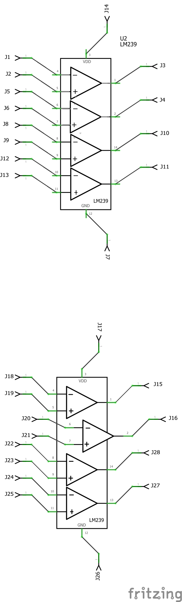
The top one in this png is your part. Note the pins are not aligned on the .1 grid and the pin numbers don’t match breadboard or pcb. The connectors (J1-J14) match the pin numbers in Breadboard and PCB, but in schematic they go to the wrong pins. The connector lines are connecting in the middle of the pin because the teminalId is a group, and that won’t work as a terminalId. The chip in the bottom is yours with the problems corrected and subparts added. The difference subparts makes is that each individual comparitor can move (as comparitor2 is in the image) independent of any of the others. Your schematic happens to be laid out correctly do subparts so I added them. Below is the improved version of your part (which I would encourage you to submit to Fritzing-parts on github to be included in core) and the test sketch the image is from so you can see the differences.
edit:
Replaced both files with a version that has the pin numbers corrected. Comparitors 1 and 2 were reversed.
LM239-improved.fzpz (9.6 KB)
test-Sketch.fzz (51.3 KB)
Peter