Synth-DIY multi-part bin

A backup of my most recent parts bin:
MyPartsFeb2019.fzb (13.9 KB)

Containing mostly analog-audio and synth-DIY orientated parts.
Most are made as multi parts (where applicable).

MULTIPARTS

TL072
TL074
LM13700
CD4066
CA3080
CD40106
CD4013
CD4015
CD4024
CD4070
CA3046
CA3096
NE570
LM339
LM3914
LM3900
V2164

OTHER

TL071
NSL-32SR3
PT2399
74LS04
74LS08
SN7432
SN76477
CEM3340
LM308
ATTiny84
2N3819
78L05
79L05
LT44
MPF102

1 Like

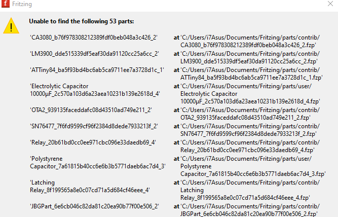
This looks really cool. I want to use them to make breadboard layouts for kids to make synth circuits. Unfortunately when I tried to open it I got an error that it couldn’t find the parts. It looks like it refers to a whole lot of .fzp files in your documents/fritzing/parts/contrib folder…
Could you make a zip file of those?

image

Better late than never? :stuck_out_tongue:

1 Like

Damn straight :smiley: I’m going to put these to good use.

1P4T Switch.fzpz (5.2 KB)
2N3819.fzpz (5.6 KB)
6N137.fzpz (6.4 KB)
74HC595.fzpz (6.9 KB)
74LS04 - V2.fzpz (7.3 KB)
74LS04.fzpz (7.0 KB)
74LS08 - V2.fzpz (8.0 KB)
74LS08.fzpz (7.7 KB)
74LS32 - V2.fzpz (8.8 KB)
74LS32.fzpz (8.6 KB)
78L05.fzpz (5.9 KB)
79L05.fzpz (5.9 KB)
555 Timer.fzpz (5.6 KB)
Alpha Potentiometer Angled Thonk .fzpz (7.3 KB)
Alpha Potentiometer Thonk .fzpz (7.1 KB)
AS3320.fzpz (8.3 KB)
ATMEGA328P.fzpz (9.3 KB)
ATTiny84.fzpz (9.0 KB)
Bridge Rectifier - V2.fzpz (5.0 KB)
Bridge Rectifier.fzpz (4.6 KB)
CA3046.fzpz (6.7 KB)
CA3080.fzpz (5.8 KB)
CA3096 - V2.fzpz (6.2 KB)
CA3096.fzpz (9.3 KB)
CD4013.fzpz (8.8 KB)
CD4024.fzpz (6.5 KB)
CD4046.fzpz (6.6 KB)
CD4066.fzpz (198.9 KB)
CD4070.fzpz (7.9 KB)
CD40106.fzpz (9.4 KB)
CEM3310 ADSR.fzpz (9.3 KB)
DPDT Relay.fzpz (6.4 KB)
DPDT Switch.fzpz (8.7 KB)
eBay Potentiometer.fzpz (17.0 KB)
Electrolytic Capacitor.fzpz (7.9 KB)
Heatsink.fzpz (4.7 KB)
I2C LCD.fzpz (7.2 KB)
JST Header 2-Way.fzpz (4.0 KB)
Latching Relay.fzpz (6.2 KB)
LM308.fzpz (8.5 KB)
LM317 - Voltage Regulator.fzpz (9.4 KB)
LM337 - Voltage Regulator.fzpz (8.8 KB)
LM339.fzpz (8.4 KB)
LM3900.fzpz (8.3 KB)
LM3914.fzpz (7.0 KB)
LM13700 - V2.fzpz (8.4 KB)
LM13700-V1.fzpz (9.0 KB)
LT44 Transformer.fzpz (5.8 KB)
MCP4822.fzpz (5.7 KB)
MPF102.fzpz (5.6 KB)
NE570.fzpz (10.9 KB)
Optocoupler.fzpz (4.9 KB)
PIC16F628.fzpz (7.3 KB)
PJ301BM 3.5mm Jack.fzpz (5.7 KB)
PJ302M.fzpz (4.7 KB)
Polystyrene Capacitor.fzpz (6.8 KB)
PT2399.fzpz (6.6 KB)
Rectifier Diode.fzpz (5.1 KB)
RELAY.fzpz (18.7 KB)
SN76477.fzpz (7.9 KB)
Stereo Audio Jack.fzpz (5.4 KB)
THAT 2180 VCA.fzpz (5.3 KB)
Thonk Alpha Dual Potentiometer.fzpz (12.0 KB)
TL071.fzpz (8.5 KB)
TL072.fzpz (13.3 KB)
TL074 Quad Opamp (Movable).fzpz (9.0 KB)
Trimpot 3362P.fzpz (10.1 KB)
V2164.fzpz (7.0 KB)
Voltage Regulator - 5V.fzpz (5.1 KB)
XR 2206.fzpz (6.8 KB)

1 Like

Good collection of parts! I expect you need to run them through FritzingCheckPart.py though.when I did so for the 1P4T Switch part I get

Error 69: File
‘svg.schematic.1P4T Switch_3959114ec473a38ddd5c77b69095772e_1_schematic.svg.bak’
At line 8

Found a drawing element before a layerId (or no layerId)

which translates to this (the schematic svg)

needs to change to this

in order for the part’s schematic to appear in an exported image of the part (svg, jpg. png etc.)

Peter

Some of the obscure parts, like the switch you mention, were made many years ago and I only made it so far as it worked for my needs. I’m sure I only used it once!
All of the parts are working but some might not work on the breadboard as I only use Fritzing to make PCBs so I never even look at BB view. Feel free to modify any parts that might be useful!
Hopefully these will do the job for most DIY synth folks.

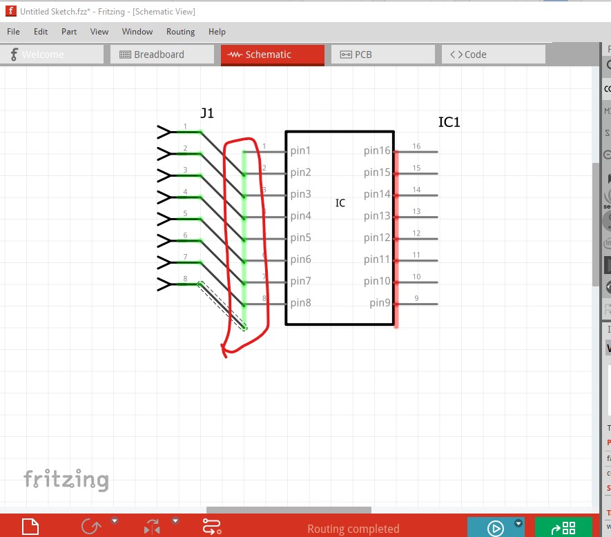
Great to see this list, but not sure if I’m doing the right thing with it. I want a CD4046 part (CMOS PLL) for a project schematic/layout so this looks ideal as it is in the list, but when I download it it just shows a 16-DIP package with no pin information other than the numbers - is this correct please? Even that would be useful but wondering if something has been lost?

In addition to that the schematic appears to be incorrect in that the pins are offset by 1 pin all the way down.

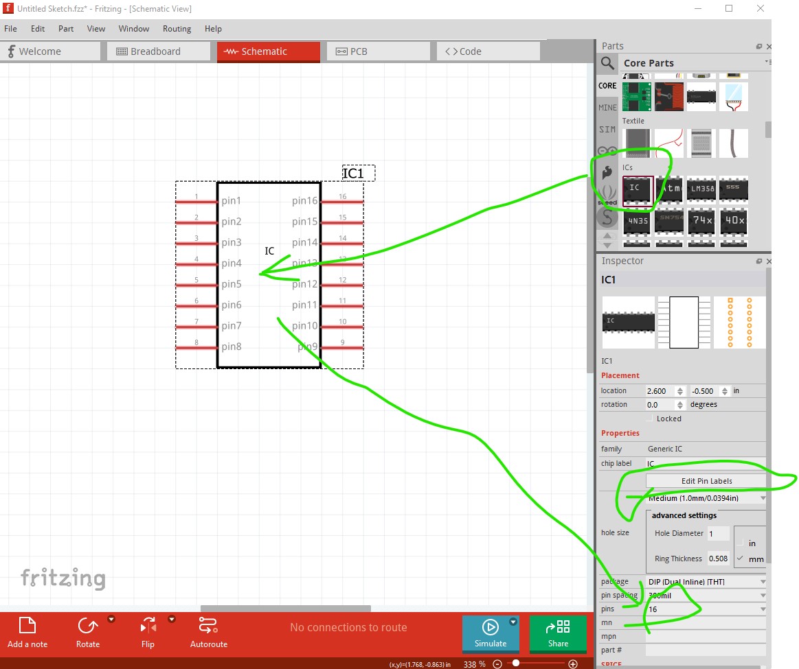
It looks like a generic IC was used and the pins weren’t edited (so you get the default pin number as a labels.) You can do the same thing by dragging the generic IC in to the sketch, then setting it to 16pins in Inspector and clicking on the edit pin labels tab which will let you name the individual pins.

The alternative is to make a custom schematic svg (which is a fair bit harder!)

Peter

Thanks Peter for the very quick response - the offset pins was another issue I noticed! I’ve created my own part as you suggested.

hello, i have a probleme with this loot, he didn’t simulate its normal ?

Yes, it is very likely (I haven’t actually checked but you can like this, this is the XR2206 part) that it doesn’t have a spice model in the part (and indeed it does not!):

As you see in Inspector on the bottom right (circled in red here) there is no spice data present and the part thus won’t simulate. In general the digital chips don’t have spice models and won’t simulate, but this is an analog chip and would simulate if it had a spice model (I don’t know if there is a spice model for it though either.)

Peter

ho … i don’t fund spice modele :cry:

hiI found a way that seems close to SPICE by changing some of the code, but it doesn’t actually perform its functions. After spending two days trying to simulate the 40106, I was wondering if you know any other software or alternatives I could use to practice creating VCOs, VCFs, and FX
either in this software or in another one?
Or maybe you have some tips or methods so I can train myself better?

Thanks!

While I am far from an expert on spice (@fai who wrote the simulator will hopefully comment as he know far more than I) I don’t think that spice will do simulation of digital circuit (although I could be wrong.) You would need to add the spice model (assuming you can find one, I am not aware of spice models for digital circuits although they may exist) to the 40106 part in a custom part which also isn’t particularly easy.. If you are looking for digital simulation tinkercad may do what you want. I looked at it but it is cloud based (which I dislike) and Fritzing better suits what I do. I haven’t really looked at what is available for simulation all that much so others may have better suggestions.

Peter

Here is a test of 40106 for spice with gemini I don’t know anything about code so I had to ask him but would it be possible to do something with this? It would be fun to create vco, vcf, and fx on this great software CD40106_SPICE_XML_FIXED.fzpz (9.7 KB)
jai cette erreur Errors:
stderr Error: Could not find include file spice/cd40106.lib

I don’t know enough about spice to identify the problem here. I expect @fai can give you an answer though. I suspect that it is not finding the spice library but I don’t know how to tell it to do so.

jai cette erreur Errors:
stderr Error: Could not find include file spice/cd4010

In the .fzp file for your par the spice definition (I think!) is looking for the cd40106.lib and not finding it, but I don’t know how you tell it where it is (or if you can for that matter, it may need to be added to the code in Fritzing!)

  <spice>
   <line>* CD40106B Hex Schmitt-Trigger Inverter SPICE Model</line>
   <line>* Pin mapping: 1=A1, 2=Y1, 3=A2, 4=Y2, 5=A3, 6=Y3, 7=VSS, 8=A4, 9=Y4, 10=A5, 11=Y5, 12=A6, 13=Y6, 14=VDD</line>
   <line>.SUBCKT CD40106B 1 2 3 4 5 6 7 8 9 10 11 12 13 14</line>
   <line>* Schmitt Trigger Inverter 1 (pins 1-2)</line>
   <line>XINV1 1 2 14 7 CD40106_INVERTER</line>
   <line>* Schmitt Trigger Inverter 2 (pins 3-4)</line>
   <line>XINV2 3 4 14 7 CD40106_INVERTER</line>
   <line>* Schmitt Trigger Inverter 3 (pins 5-6)</line>
   <line>XINV3 5 6 14 7 CD40106_INVERTER</line>
   <line>* Schmitt Trigger Inverter 4 (pins 8-9)</line>
   <line>XINV4 8 9 14 7 CD40106_INVERTER</line>
   <line>* Schmitt Trigger Inverter 5 (pins 10-11)</line>
   <line>XINV5 10 11 14 7 CD40106_INVERTER</line>
   <line>* Schmitt Trigger Inverter 6 (pins 12-13)</line>
   <line>XINV6 12 13 14 7 CD40106_INVERTER</line>
   <line>.ENDS CD40106B</line>
   <line>* Subcircuit for single Schmitt trigger inverter</line>
   <line>.SUBCKT CD40106_INVERTER IN OUT VDD VSS</line>
   <line>* Real CD40106 Schmitt trigger implementation</line>
   <line>* Using behavioral source for hysteresis</line>
   <line>EOUT OUT 0 VALUE={IF(V(IN) GT 2.8, 0, IF(V(IN) LT 2.2, 5, V(OUT)))}</line>
   <line>R1 OUT 0 1K</line>
   <line>C1 OUT 0 1P</line>
   <line>.ENDS CD40106_INVERTER</line>
  </spice>

Unfortunately I don’t know enough to give you a better answer.

Peter

did not have much time today, but it seems that you have defined two nested subcircuits, but you are not using the CD40106B subcircuit. You must define it and use the right connectors, see the spice of a transistor for example.

In any case, I am not sure how you get the “stderr Error: Could not find include file spice/cd4010“ error as I do not see any call to a library. Please, submit a minimum but full circuit with the chip and a power supply, etc.

Check this too:

By this I think @fai is requesting that you upload the .fzz file file of the sketch that creates the error (this is always a good start when asking for help!) Upload is 7th icon from the left in the reply menu and will accept .fzz and .fzpz file (which as you uploaded a .fzpz I expect you already know :slight_smile: .)

Peter