this is a continuation of
Here we are going to look at creating parts with schematic subparts. The purpose of schematic subparts are to allow elements of a multi element part (such as a dual op amp or a hex inverter) to move around schematic independently. I will use the 74x125 quad tristate buffer as an example of this. We will look only at the schematic svg and the fzp file as they are the only two files that are affected by this. Note that schematic subparts block the use of buses in the same part, I don’t know why and fixing that is a desirable enhancement but at the moment, subparts block the use of buses. First the 74x125.fzpz file so you can load it in to Fritzing and see what it does, and unzip it to get the fzp and schematic svg files that make up the part:
74x125.fzpz (9.6 KB)
Then an illustration of the standard part (top) and the standard part with the subparts moved independently to demonstrate their use:
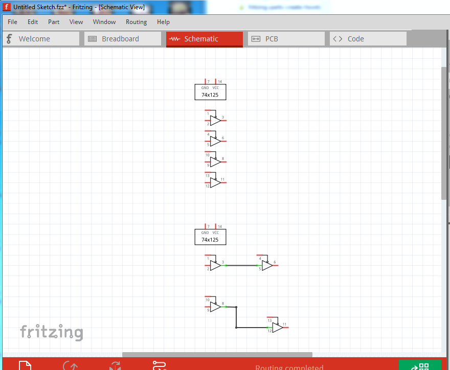
as we see each of the 4 parts in the package can be moved independently of any of the others. So let us look at how to configure this (note, you must edit the fzp file via a text editor as the Parts Editor does not currently support subparts.) Lets start by looking at how the schematic svg needs to be laid out.
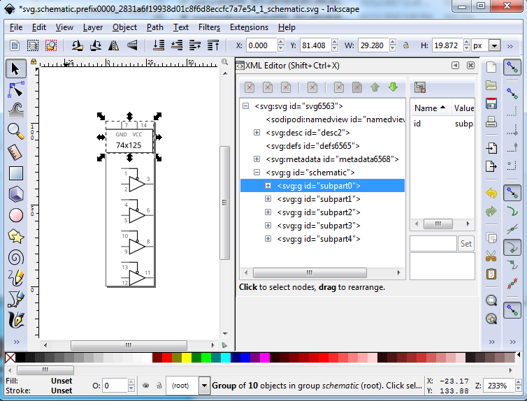
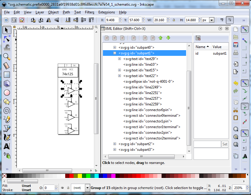
This is fairly simple, the power and ground connections are one independent element in a group called subpart0, The 4 individual gates are contained in 4 groups called subpart1 to subpart5 (with more elements in additional groups if needed.) All the elements of a group need to not overlap the elements of another group. Here is subpart1 (the first independent element) as an example of this. Note all parts of the element including the connections are enclosed in the group.
Now we move on to the fzp file which is the other place that requires configuration. The connector section is standard, like any other part, 14 connectors in this case:
....
<connectors>
 <connector id="connector0" type="male" name="C1">
   <description>Control 1</description>
   <views>
     <breadboardView>
       <p svgId="connector0pin" terminalId="connector0terminal" layer="breadboard"/>
     </breadboardView>
     <schematicView>
       <p svgId="connector0pin" terminalId="connector0terminal" layer="schematic"/>
     </schematicView>
     <pcbView>
       <p svgId="connector0pin" layer="copper0"/>
       <p svgId="connector0pin" layer="copper1"/>
     </pcbView>
   </views>
 </connector>
 ....
 <connector id="connector13" type="male" name="VCC">
   <description>VCC</description>
   <views>
     <breadboardView>
       <p svgId="connector13pin" terminalId="connector13terminal" layer="breadboard"/>
     </breadboardView>
     <schematicView>
       <p svgId="connector13pin" terminalId="connector13terminal" layer="schematic"/>
     </schematicView>
     <pcbView>
       <p svgId="connector13pin" layer="copper0"/>
       <p svgId="connector13pin" layer="copper1"/>
     </pcbView>
   </views>
 </connector>
</connectors>
After the connectors are defined we now have a new optional section of the fzp that defines the subparts. It looks like this:
      <schematic-subparts>
        <subpart id="subpart0" label="">
          <connectors>
            <connector id="connector6"/>
            <connector id="connector13"/>
          </connectors>
        </subpart>
        <subpart id="subpart1" label="1">
          <connectors>
            <connector id="connector0"/>
            <connector id="connector1"/>
            <connector id="connector2"/>
          </connectors>
        </subpart>
        <subpart id="subpart2" label="2">
          <connectors>
            <connector id="connector3"/>
            <connector id="connector4"/>
            <connector id="connector5"/>
          </connectors>
        </subpart>
        <subpart id="subpart3" label="3">
          <connectors>
            <connector id="connector7"/>
            <connector id="connector8"/>
            <connector id="connector9"/>
          </connectors>
        </subpart>
        <subpart id="subpart4" label="4">
          <connectors>
            <connector id="connector10"/>
            <connector id="connector11"/>
            <connector id="connector12"/>
          </connectors>
        </subpart>
      </schematic-subparts>
    </module>
The layout is similar to buses. Each subpart has a label (which needs to match the group id in the svg file) and a list of the connectors that make up the subpart. The connectors can only be in one subpart and as noted the part can not (at present at least) have buses defined. One drawback of subparts is a lot of them (around 10 to 12) in a sketch will start to slow rendering down. Presumably the more subparts present the slower rendering will become. However for some parts (such as logic buffers in this case and dual or quad op amp parts) they are very useful and not that difficult to create once you know how. The FritzingCheckPart.py script understands and will catch configuration errors (in the fzp file only, not the svg so much) to help keep things straight.