Hi everyone, I’m a newby of Fritzing (1.0.1) and I need a bit help.
I am making a circuit in which there is a Heltec ESP32 WiFi V3 Oled but this is not present in the Fritzing components list.
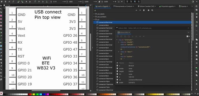
So using Inkscape I tried to modify in svg the a similar component: the ESP32 LoRa which however has different pin numbering.
I made the change in svg but the changes result are only in the schematic sheet, while in PCB has remained the original pin numbering of LoRa.
I ask you if that’s normal SVG changes are not show in PCB representation? Otherwise how is possible to adopt pin numbering which is correctly visible in schematic form?
Thanks
The first thing to do is a google search like this “fritzing part Heltec ESP32 WiFi V3 Oled” which will find parts that are not in core parts. In this case that doesn’t appear to include this board although there are number of others available. Unfortunately making parts is a complex task. These two tutorials apply to the current versions of Fritzing
and may help if you want to do it yourself. If you need a small number of boards done (such as only this one) it is usually easier to get someone like me who is familiar with making and modifying parts to do it for you. It isn’t all that difficult for me, but is likely a lot less so for you.
Peter
Thank you very much Peter for this answer and for your availability of support, I tend to try to learn by myself. When I was a boy, an old saying of Confucius was in vogue: “if you see someone who is hungry, don’t give him fish but teach him how to fish”. Obviously in this case “hungry of knowledge”.
I am grateful for your links but could you give me a short answer about the question: I don’t understand if with Inkscape (installed 2 days ago) it is possible to create svg files that update/modify both the schematics and the PCB parts.
Thanks!
Yes, Inkscape is what I use to create parts so it will do the job. Assuming you are using parts editor (I don’t, I edit the underlying files directly) it can not modify the .fzp file and thus can’t change the number of pins if the original part had more or less than the one you need. The pin definitions and labels are contained in the .fzp file. You either need to run the part through FritzingCheckPart.py (referenced in my tutorial) or edit the svgs after Inkscape with a text editor to remove the px from all the font-size entries as Fritzing doesn’t like them and will change the font size to either 0 or very large if they are left in.
Peter
If you are interested, that part is available from:
Thanks Pete for your link, unfortunately the WiFi V3 is not present in your nice collection of Heltec products.
Personally I use only this card because cost much less than the others Heltec’s (20€ instead of 30€) and now I don’t need LoRa yet.
Unfortunately in Inkscape the PCB parts are blocked from changing the pin numbering both in graphics mode and in the XML part. Yet it should be simple starting from the svg file V2 to change in V3, almost identical except for the pins and the LoRa antenna…(sob)
I’m wondering if my svg files (downloaded by Fritzings part collection) has been protected from more later changes…
@rgfFritzing, I’m not sure why you say it’s not there… It’s definitely there—I use it myself. I just clicked on the link and it’s there, in my post dated Nov '22, after the two CubeCell modules (V1 update and V2) and before the Wireless Stick Lite V3 module. It’s also available from my website, which will come up if you simply type “Fritzing WiFi LoRa V3” into your browser.
That’s right, I only found the WiFi LoRa version and not the (basic) V3 with WiFi only (without LoRa).
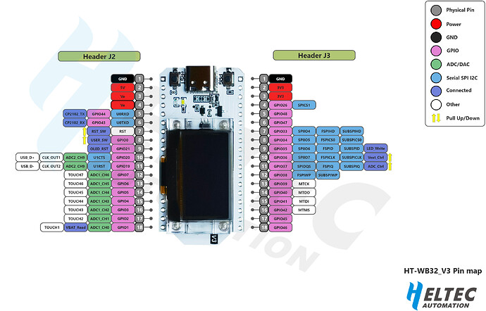
The pin numbering is completely different (see image above).
I’ll try to see if I can find it on your website
.
. .
. . .
. . . .
. . . . . . sorry, I couldn’t even find your website… (gasp)
My mistake! I missed the ‘no LoRa’ bit. I haven’t done the WiFi Kit 32 V3 yet, but I’ll have a look at it later this evening. It looks like a relatively straightforward change to what is already there (in the original ‘Kit’—no LoRa—module).
I have added the Heltec WiFi Kit 32 V3 part to the Heltec Dev Boards thread:
Let me know if I’ve missed anything…
Oh Jesus, that was just what I needed! Thanks a lot!
Could you explain me where are in Inkscape the commands to modify the PCB part?
I only found those to modify the schematic and in the xml listing I didn’t find any PCB references.
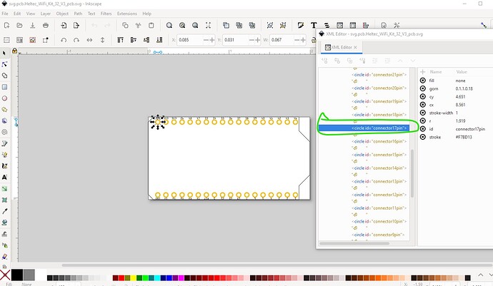
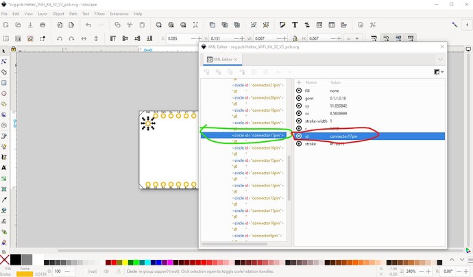
There aren’t any pcb (or any Fritzing view) commands in Inkscape, it is a general svg editor. If I needed to move connector17 down 0.1in for some reason I could do it a variety of ways. Easiest is this:
first select the object you need to move
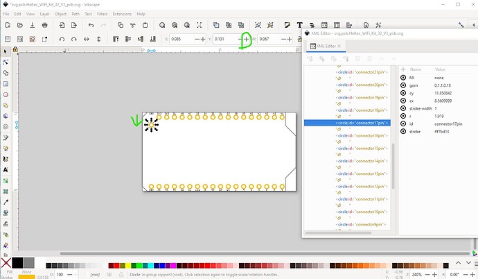
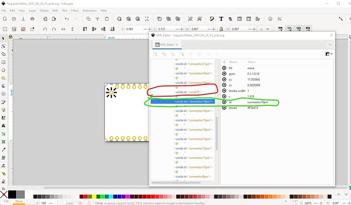
then click the + icon on the y coordinate. That moves the pad down in y by 0.1in. I could also change the value (currently 0.131in) to whatever I needed in x or y, or select the element and drag it with the mouse. For Fritzing (which wants things aligned to specific intervals) usually the increment or manual set options are the most useful. If I need to change the connector number of connector17 I would use XML editor like this:
Note that as a side effect that previous connector18pin has been replaced by circle72 because names must be unique so Inkscape renames the conflicting element id.
Peter
Just for the record, I don’t find Inkscape convenient to use on a Mac (it runs in an X11 emulator), so I use Illustrator for all of my drawing tasks (Breadboard, PCB & Schematic), import those files into the Parts Editor to create the necessary Metadata and ‘tie the views together’—this also automatically corrects Illustrator’s dimensioning ‘problem’—export the part from the Parts Editor, unpack that using the fzpzclean.py script and correct the current Parts Editor shortcomings with a regular text editor, before running the component files through the FritzingCheckPart.py script. And there’s often a ‘wash, rinse, repeat’ cycle in there to correct errors…
As @vanepp says, however you do it, a little more complicated than just a few commands in any editor…
Excellent explanation!
Thank you both
