Sorry, I completely missed that you had posted the original svg file at the start of the post. OK I think I have figured out what went wrong and where a number of bugs are. The good news is that I also managed to salvage your svg and correct the part so it works correctly. So lets start with that:
cd4051-fixed.fzpz (6.7 KB)
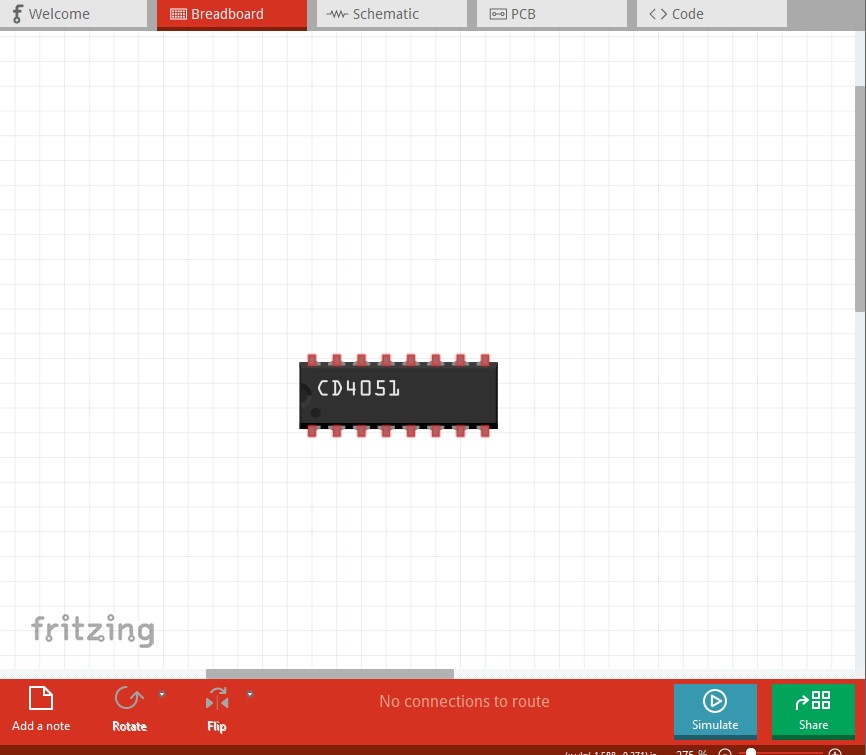
This is the corrected part which I believe now works correctly. The changes needed are documented in the rather long post to follow. To report the bugs on github I expect you will need to download the various images to your desktop then drag them in to the github window to upload them. For fritzing files (fzpz and fzz) you need to append a .zip to the end of them because github only accepts zip files (not .fzpz or .fzz.) To start I loaded the cd4051.fzpz first to Fritzing 0.9.10:
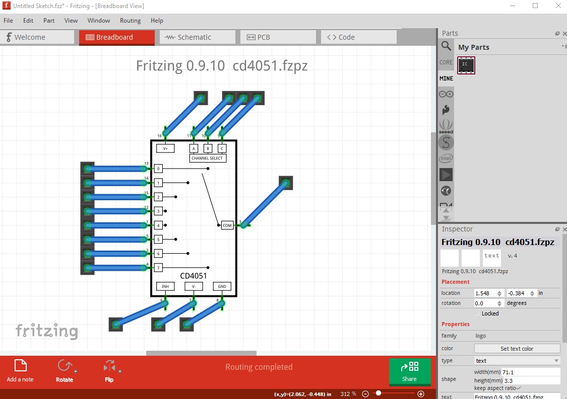
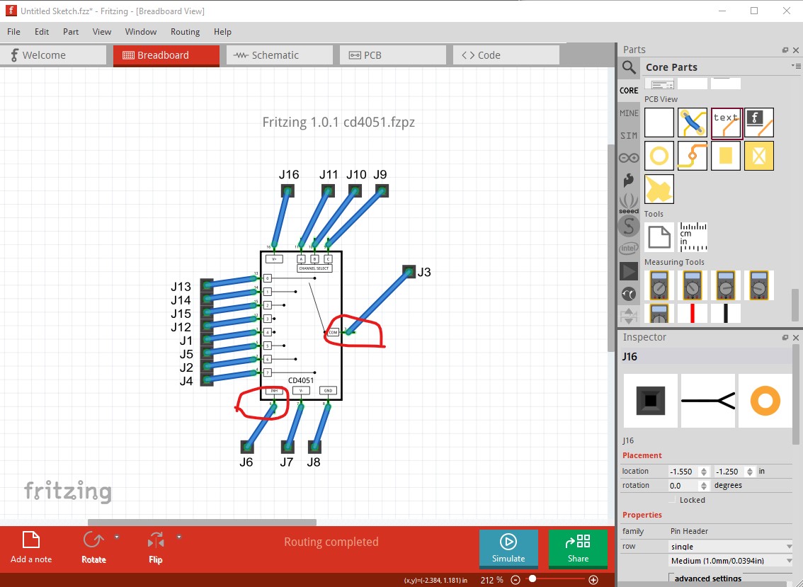
The first problem is you managed to upload the schematic svg in to breadboard (in the fized part I replaced it with a 16 pin dip breadboard svg.) That svg has no terminalIds so the wires connect to the middle of the pin not the end as they should. Other than that (and the schematic image in breadboard) this appears to work fine. All the connections go to the correct place and all looks happy. On to schematic:
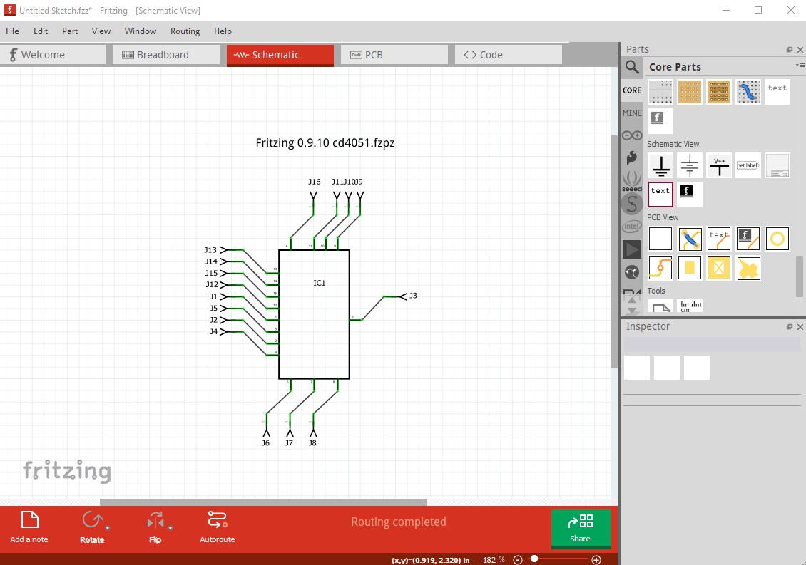
Other than the lack of internal connections (likely a Fritzing 1.0.1 parts editor bug) it looks fine in 0.9.10.
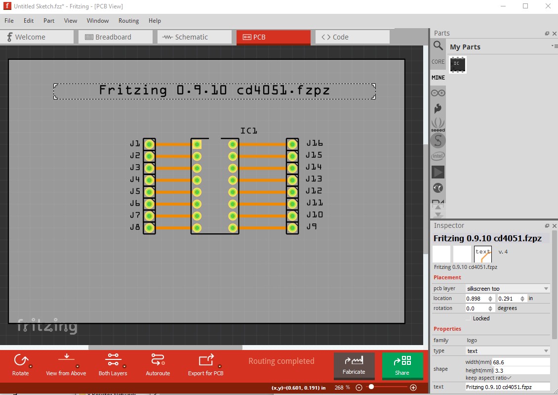
pcb is also fine.
So on to Fritzing1.0.1:
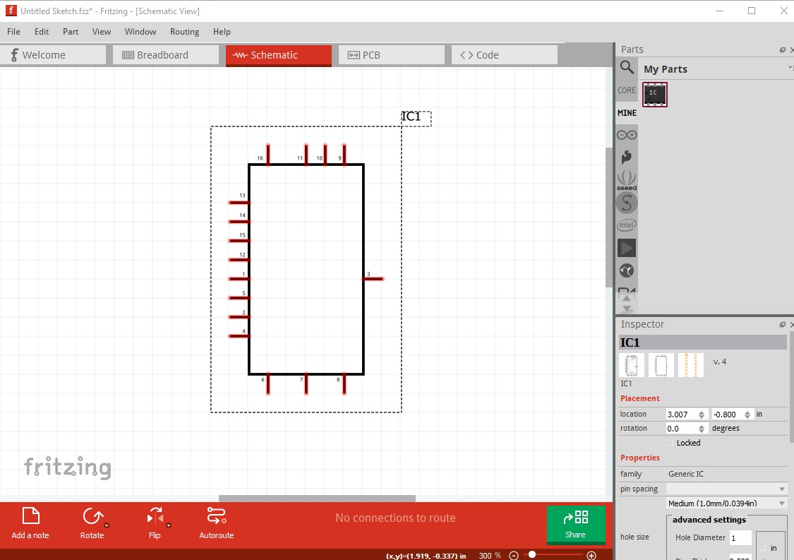
breadboard is much the same as 0.9.10, schematic is much more broken!
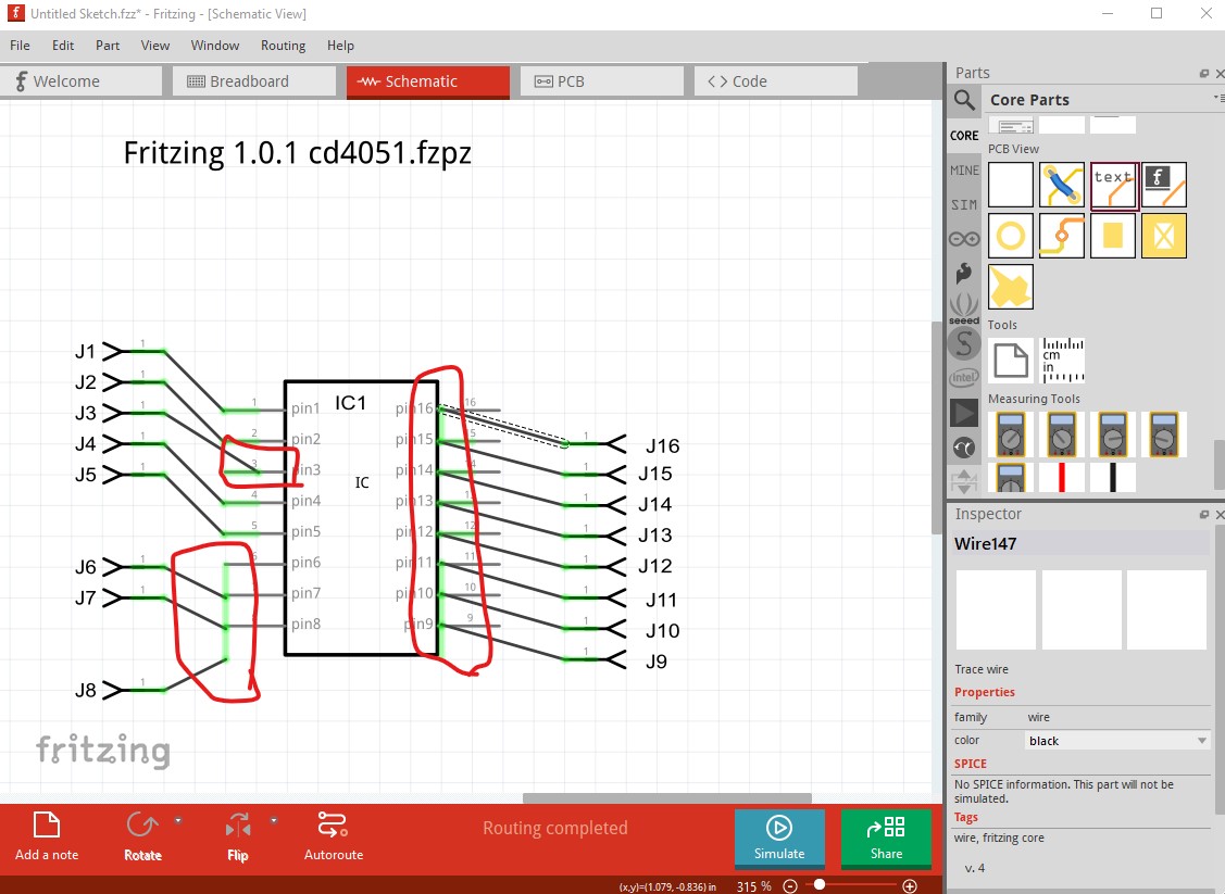
Even though the terminalId is present in both the .fzp file and the svg it isn’t used in connector3terminal (it is unclear why.) In addition text from the generic IC (which is not in the schematic svg which was loaded) has been added from somewhere, and the pins are misplaced (again not like in the svg!) There appear to be a number of bugs here.
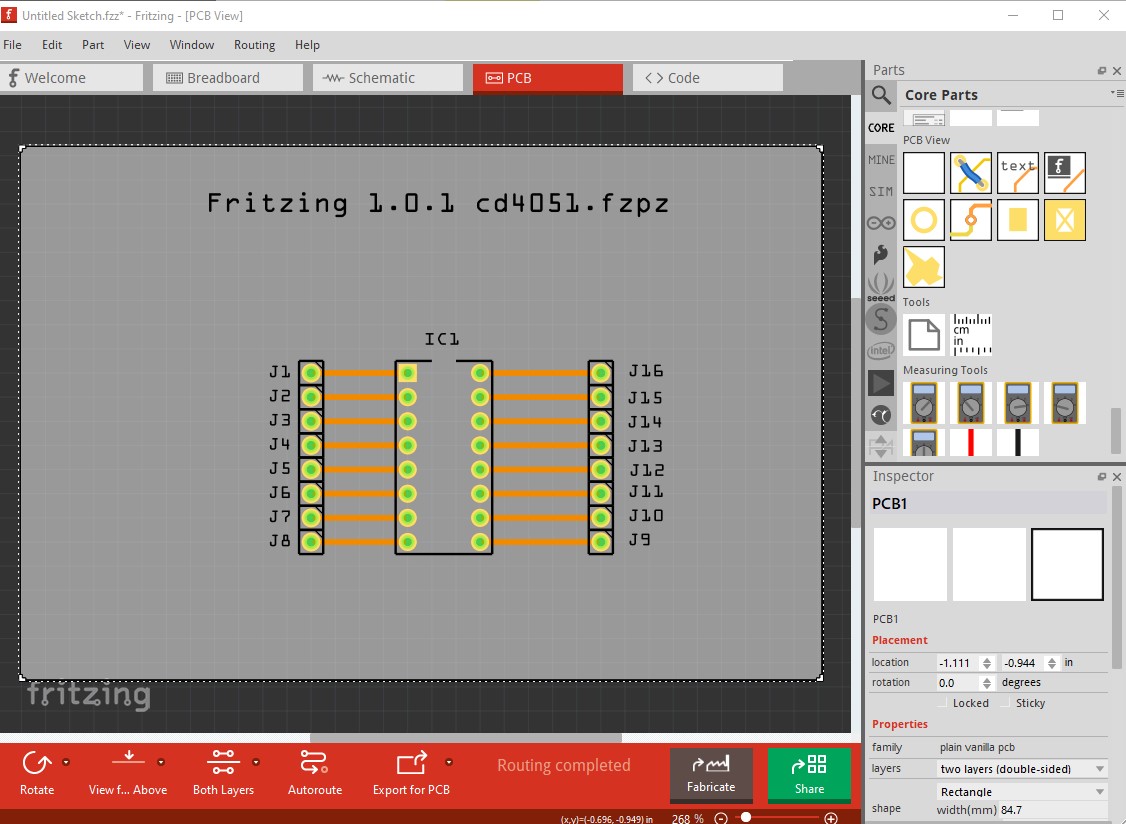
again pcb looks normal. With the apparent bugs detailed, lets move on to problems in your svg and how I fixed them. The first problem is you look to be using Adobe Illustrator, which is OK except it isn’t as configurable as Inkscape and specifically there doesn’t appear to be a way to set the dimensions to either in or mm (I have read the online Illustrator documentation without finding a way to set this.)
There is a suggestion of what to set from some time back, I don’t know if it works or not but may help
although it doesn’t look like it (the attached svg is dimensioned in px!)
Here is a recent post of what an Illustrator user does to get Illustrator svgs in to Fritzing
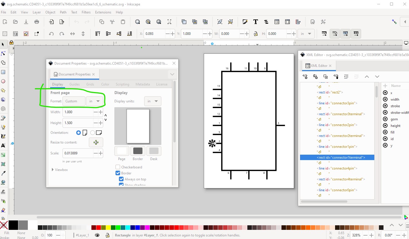
That said on to the problems with your svg.
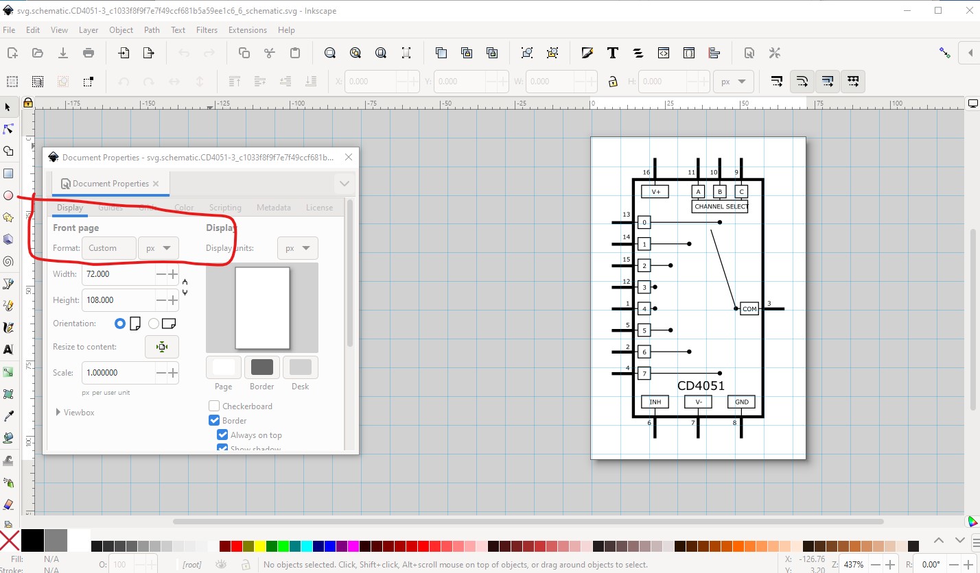
here I loaded your svg in to Inkscape. As we see the dimension is set to px (which Inkscape assumes means 96dpi and Illustrator typically sees as 72dpi.) If you look at the image (the grid lines are on 0.1in boundaries) you can see the scaling issue. The various wires should be on 0.1in boundaries and they are not. To fix that I changed the dimension to inches then rescaled the entire svg til the lines were again on 0.1in boundaries.
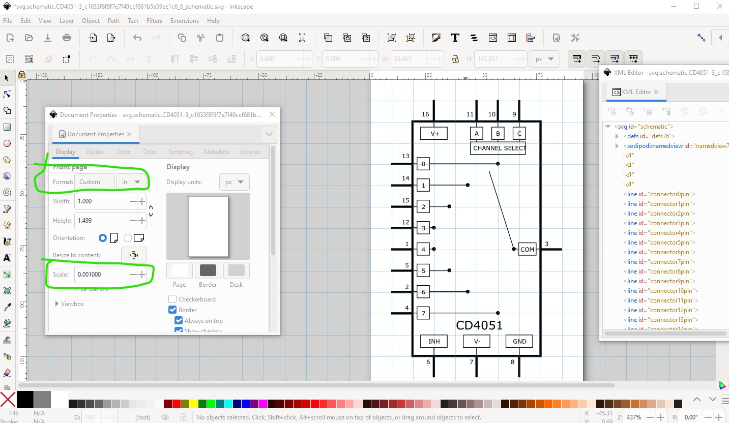
on the way by I changed the scale to be the desirable 1 drawing unit = 1/1000in.
somewhere in the ungroup and rescale I lost your terminal definitions (they are there in the original svg though!) so I replaced them with a 10thou by 10thou rectangle with fill=none, stoke=none and stroke-width=0, then positioned them on the end of the pin. I also set the stroke-linecap to round, and the line color to #555555 to match the graphics standard. Then in the fzp file I changed a few fields
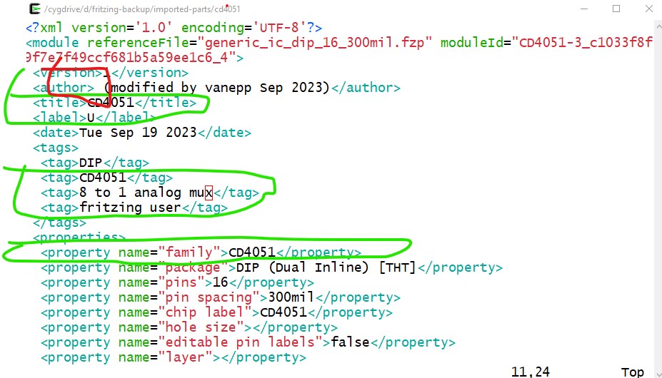
You need to add you name in the author field. I changed the family from “Generic IC” (which is a flag to Fritzing that this is a parts factory part which you don’t want!) to CD4051
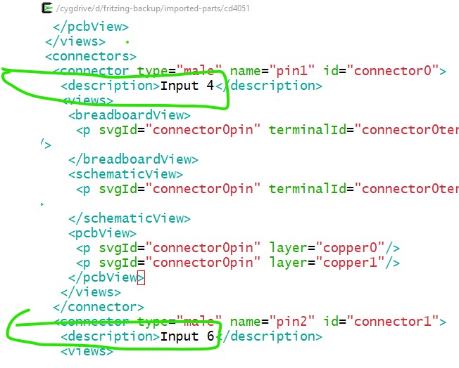
then I added names to all the description fields. As noted above the breadboard svg is currently a copy of the schematic svg so I replaced that with a generic 16 pin dip svg.
I also in the schematic svg changed ‘DroidSans-Bold’ (which isn’t a valid Fritzing font) to ‘Droid Sans’ which is a correct Fritzing font. It appears to me that the problem occured in this step (this is editing the original fzpz file in Fritzing 1.0.1 parts editor and trying to replace the schematic svg image.)
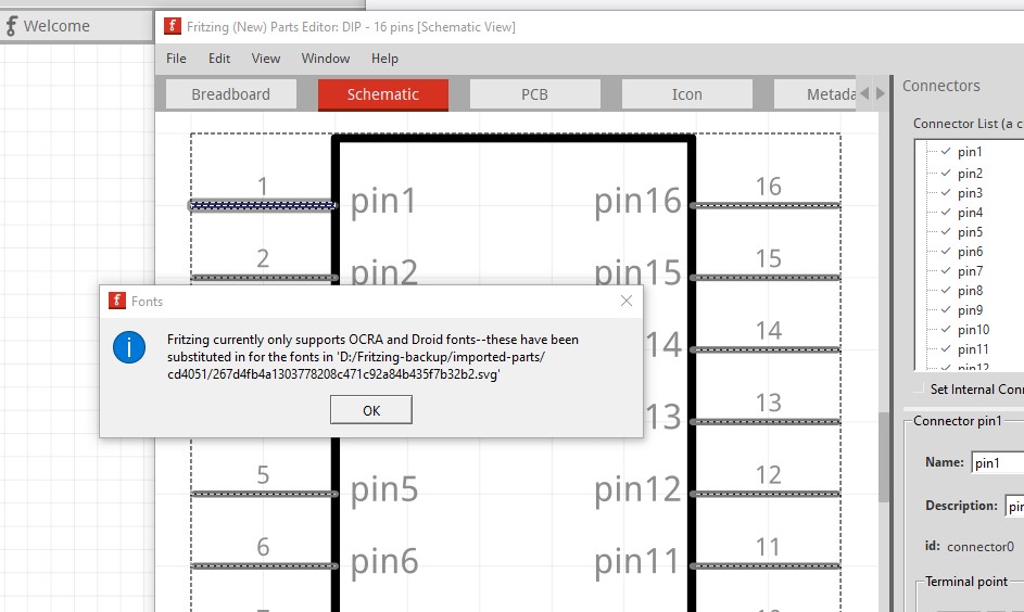
clicking OK here appears to corrupt the schematic svg (Fritzing 0.9.10 correctly translates the fonts) indicating that 1.0.1 has a bug in the font substitution code. The resulting svg looks like this which is incorrect:
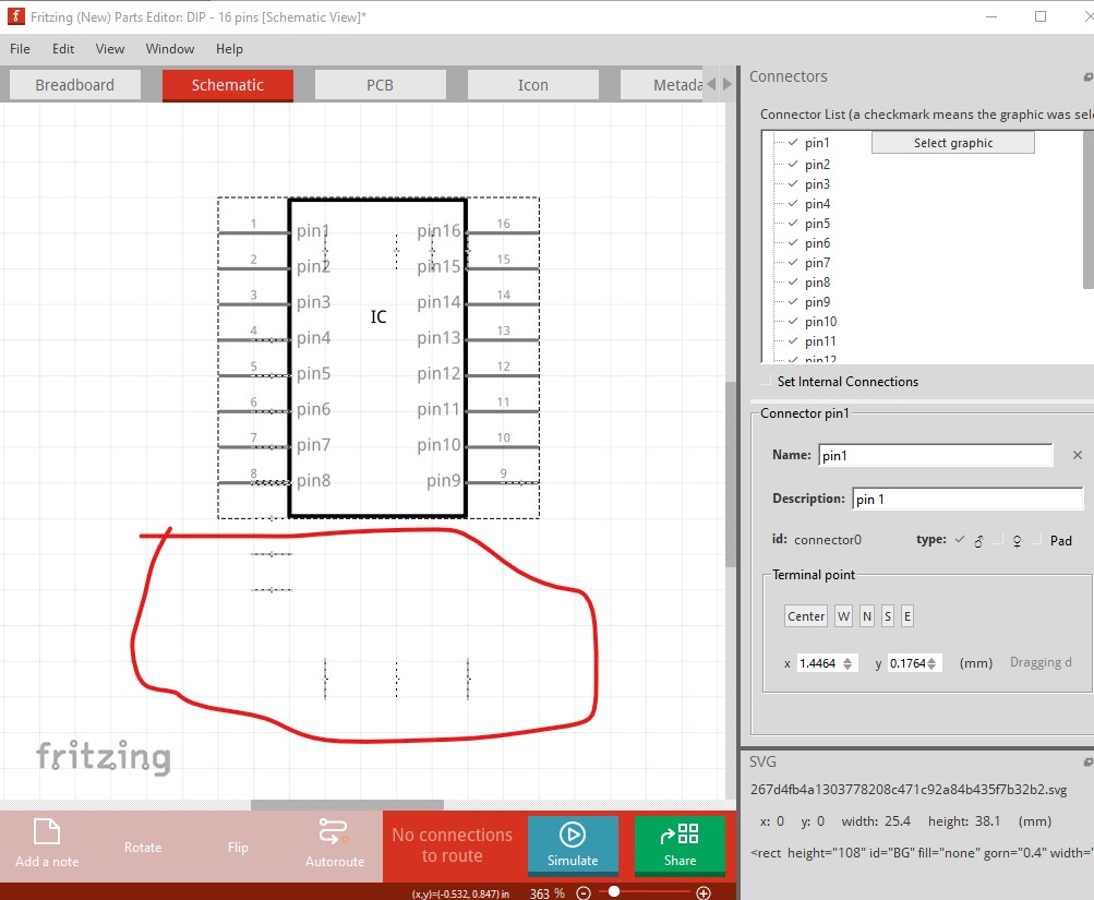
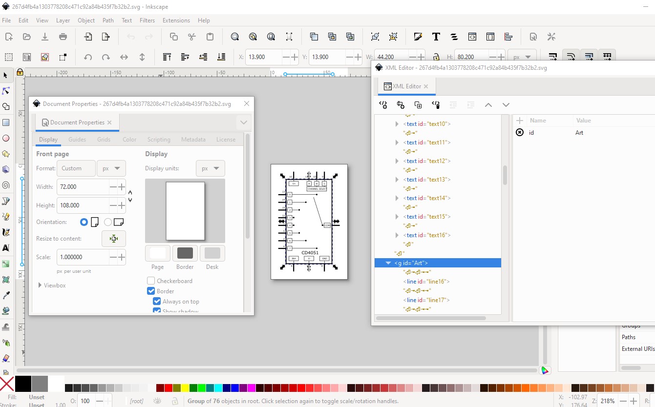
The internal connections getting lost appears to be that parts editor for some reason decided to delete this group named “Art” which contains all the internal connections. I don’t know why that happened as the group is not unusual in any way I can see, perhaps one of the developers will see something I didn’t. That appears to be why there are no internal connections in the schematic svg. though.
As noted all my changes are in the cd4051-fixed.fzpz
part which appears to work correctly. Hope this helps!
edit
Since I’m here, I will open an issue on github for the bugs found
here.
edit2:
bug filed here
Peter