Heltec Dev Boards

This looks good! Did you find a way to change the dimensions from px to in in Illustrator or copy an svg already set to in? One small nit: in pcb group Pin_Holes isn’t needed. They are grey circles overlaying the pads although they currently don’t render in Inkscape (I’m not sure why because they should as far as I can see!) but will be ignored by Fritzing.

Peter

I can’t find anything in Illustrator to do the unit conversion, and based on my search efforts no one else has been able to either. But it does seem that all I really need to do is to manually calculate the converted dimensions (i.e. divide the pixel dimensions by 72) and simply change the “height” and “width” parameters at the head of the SVG file [in a text editor] to the resulting values (e.g. height=“134.363px” to height=“1.866153in”), although the ‘safest’ way to do things at the moment is to just use the Parts Editor. I’d be happy to do everything with an appropriate text editor (like I see you doing with Inkscape, but Inkscape, as I’ve mentioned, is just too much of a pain to use on a Mac), but there are still some things that the Parts Editor does for me that I don’t know how to do myself.

My current process involves:

  1. Preparation of the relevant artwork in Illustrator;
  2. Saving, in SVG format, the individual ‘subsets’ of this artwork that comprise the breadboard, pcb and schematic elements of the Fritzing part—the pcb artwork is invariably based on the breadboard artwork, with appropriate changes to colours, and sizes if this is required to create the right sized pcb elements (per the above discussion). At this point, all of these files are dimensioned in pixels, as is Adobe’s want
  3. Creating a new part in the Fritzing Parts Editor, at this stage using a closely related part from the existing library as the initial base. I would actually be happy to start from scratch, but this does not seem to be an option at the moment;
  4. Replacing each of the views with the artwork for my part;
  5. Updating the relevant metadata and connector details;
  6. Linking individual pins in individual views to the respective connectors;
  7. Saving the new part with an appropriate name, then exporting the part file. At this point, the essential ‘pixel’ units have been automatically converted to inches by the Parts Editor, some additional ‘Fritzing’ header information has been added to the SVG files and the little boxes that are the connection points in the Schematic view, have been inserted into that SVG file. The fzp file, containing all of the metadata and relationships between this and the individual views has been created and everything has been ‘zipped’ into the new part fzpz archive file.
  8. I then run the resulting fzpz file through your ‘parts washer’, which expands the archive;
  9. Next I change the names of all of these files, and their internal references, to those that are to be used in the final part (I’m not sure if the naming details are provided elsewhere, or whether I just worked them out along the way);
  10. I then run the FritzingCheckPart Python script over these files. If I’ve done everything ‘according to Hoyle’, I get a [more or less] clean bill of health. If not, it’s a case of ‘Wash, Rinse, Repeat’, going back to the relevant point required to fix whatever problem is exposed. There are several warnings that I regularly get at this stage that would appear to be the result of my using Illustrator way back at the beginning, but none of these appear to be critical.

And those ‘Pin Holes’ should never have been there. I think they will just have been an artifact carried over from the origiinal artwork and because they were never rendered I just didn’t notice that they were still there. This was the first part I made, so my process wasn’t as refined back then.

In addressing the current issue (increasing the pad/hole sizes) I have also discovered a problem with the way Illustrator deals with unit conversion. No matter what units I use, I find that I can enter exactly the same number in two different locations—e.g. x and y values—but occasionally end up with two different numbers if I change the units (through the Illustrator Preferences—only in the third or fourth decimal place, but occasionally they’re different).

As a result, there’s now a step ‘9a’ in the above sequence, where I check the PCB SVG file to ensure that the radius of all of the holes that are supposed to be the same, are indeed the same. The error is only ever in the third or fourth decimal place, so it probably doesn’t matter, but it can produce a ‘messy’ Gerber drill file—two or three different hole sizes for what should be the same size holes, although the fabrication process may not ultimately differentiate between them.

Yes this is a consequence of using floating point. The round offs cause small errors. One of the things I hope to make FritzingCheckPart do eventually is round off all the numbers (or at least most of them) to 2 or 3 digits after the decimal which should cure this problem, but I’m not there yet.

Peter

See how you go with this one (pads 1.447mm/0.058in).
Amica_NodeMCU_DevKit_1.0 (v2).fzpz (56.8 KB)

This one works and the NodeMCU amica fit without problems

Rather than start a new post, I thought I’d keep everything in one place and add these parts for recently released updates to the Heltec Dev Boards here.

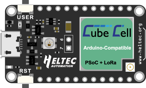
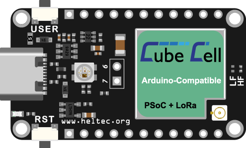
The CubeCell V2 update is pin-compatible with the original, but I’ve also updated the PCB and Schematic elements of the original part, so they’re both included. The only real difference between the two is some minor changes to the Breadboard view to reflect the presentation of the updated module.

HeltecCubeCellDevBoard

Heltec CubeCell Dev-Board.fzpz (54.0 KB)

EDITED: Please note, this part file has been corrected in line the recommendations offered below in this thread.

HeltecCubeCellDevBoardV2

Heltec CubeCell Dev-Board V2.fzpz (62.2 KB)

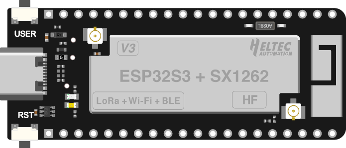
The WiFi LoRa 32 V3 and Wireless Stick Lite V3 parts are based on a new ESP32-S3 processor so, while they each share the same form factor as their respective predecessors, they are not pin compatible with earlier (V1 & V2) versions.

HeltecWiFiLoRa32V3

Heltec WiFi LoRa 32 V3.fzpz (58.4 KB)

Heltec Wireless Stick Lite V3.fzpz (59.7 KB)

1 Like

I ran FritzingCheckPart.py against the files which detects the following error:

$ FritzingCheckPartw.py part.Heltec_CubeCell_Dev-Board.fzp

Error 69: File
‘svg.breadboard.Heltec_CubeCell_Dev-Board_breadboard.svg.bak’
At line 25

Found a drawing element before a layerId (or no layerId)

This will cause the part to not export as an image (svg, jpg, png etc.) to fix it, do an Edit->select all then Object->group (assuming Inkscape!) then name the resulting group “breadboard”

$ FritzingCheckPartw.py part.Heltec_CubeCell_Dev-Board_V2.fzp

only warnings which don’t affect functionality so fine as is.

$ FritzingCheckPartw.py part.Heltec_WiFi_LoRa_32_V3.fzp

Again only warnings which don’t affect functionality so fine as is.

FritzingCheckPartw.py ‘part.Heltec_Wireless_Stick_Lite_V3.fzp’

Again only warnings which don’t affect functionality so fine as is.

Peter

My first reaction was “Gee, I ran FritzingCheckPart on that and it didn’t report any errors…”. Then I looked again at the output and, sure enough, it did! But the strange part is that I didn’t change anything in the breadboard file, so that problem’s been there all along.

Fixing it was slightly more complicated because I use Illustrator, but all should be OK now.
EDITED: Following the recommendation offered by @microMerlin below, I have amended the file available through the link above.

As a matter of interest though, when we rectify a problem like this, are we able to automatically link the new file to the old posting, or disable the old link, or have it point to the updated post automatically?

Thanks.

If you have enough privilege, you can just edit the original post with the bad uploaded part. Delete that link from the post, and upload the new one. Optionally with an “EDITED” note to explain what you did.

Thanks @microMerlin, I believe that I have modified the relevant link and included appropriate comments in the above posts.

Yep, the new file appears fine so all should be well.

Peter

I just wanted to say thank you for making the fritz file for the V3 module. A huge help, I wanted to ask if you could put something else together…https://www.amazon.com/Screw-Terminal-Breakout-Module-BeagleBone/dp/B08LKBKCDY.
I need this for a project and I tried to make it myself not working well any assistance would be appreciated!!

The B08LKBKCDY module looks like a lot of work, certainly for me because I have nothing like that upon which to build. @vanepp might be the man for that job… if he has the capacity…

1 Like

Thanks for the recommendation @UniquePete! @vanepp if you could please look into this it would be very much appreciated, I am very new to this software and this build would be great for a group of us using these. Thanks again!!

A part will be up in a bit.

Peter

1 Like

Thank you, I really appreciate it. Let me know if you need any additional details.

OK here is a part that should do what you want. I suppressed pcb as it doesn’t appear useful as this is a shield and it is set that if you stack it on top of a beagleboard black (the Adafruit one I believe) in breadboard it will connect to the shield in schematic (you however may not want that once you see what happens in schematic :slight_smile: .)

Screw-Terminal-Block-Breakout-Board-Module-for-BeagleBone-Black.fzpz (22.5 KB)

Peter

I really appreciate it, huge help! Looks great!

Once again, I figured this was the best place to keep adding Heltec parts. I have run this one through FritzingCheckPart.py.

HeltecWiFiKit32V3

Heltec WiFi Kit 32 (V3).fzpz (34.6 KB)

1 Like

Oh Jesus this is exactly what I needed! Thanks a lot!
Could you explain me where are the inkscape commands to modify the PCB part?
I only found those to modify the schematic and in the XML list I didn’t found any PCB references.