Hi All, I’ve been working on a LED controller ( By TAMIYA )
Have done all the basic parts, if your interested :
Am looking to add internals to the detail if anyone’s wanting something to do …
Cheers, Bantum …
Hi All, I’ve been working on a LED controller ( By TAMIYA )
Have done all the basic parts, if your interested :
Am looking to add internals to the detail if anyone’s wanting something to do …
Cheers, Bantum …
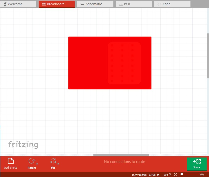
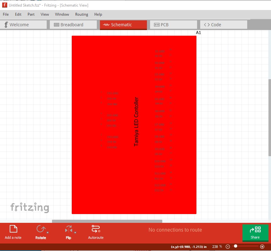
Your part is currently entirely non functional. These tutorials may be of use in fixing it:
as both apply to current versions of Fritzing. The red rectangles indicate the connections are not defined correctly.
Peter
Oppps - sorry forgot to update the .fzpz file … ![]()
Thanks for the reminder - See updated file on Github … ![]()
Ciao , Bantum …
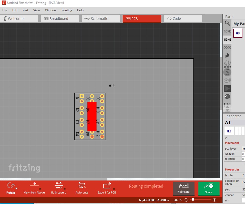
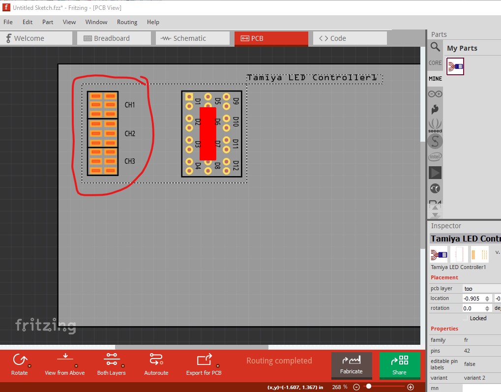
Better, but still problems. I’m unable to tell if this is intended to be the TLU01 or TLU02 (or something completely different!) as breadboard doesn’t seem to match either of them. A url that points to the web page for the part in the .fzp file is desirable. That said pcb still has a connector problem:
likely that the pads (circled in red) are SMD on the bottom of the board but the part is THT (and SMD and THT can’t in general be mixed.) The pads will have no holes drilled (as they aren’t circled) and don’t exist on the top layer (which is likely what is causing the red rectangle.) Then in breadboard, usually the connectors should be on 0.1in boundaries to align to the grid. It is possible that the connectors are supposed to be 2mm pitch rather than 0.1in though.
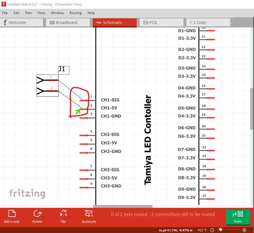
In schematic the terminalIds are missing (which FritzingCheckPart.py complains about):
Warning 14: File
‘part.Tamiya LED Controller_27a858925d35cdda1391758c1f447311_3.fzp.bak’
At line 377
terminalId missing in schematicView (likely an error)
Warning 14: File
‘part.Tamiya LED Controller_27a858925d35cdda1391758c1f447311_3.fzp.bak’
At line 392
terminalId missing in schematicView (likely an error)
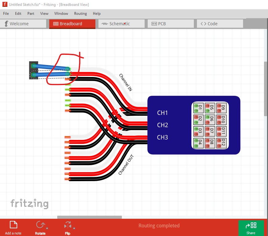
which causes the wire in schematic to connect to the middle of the pin rather than the end as it should:
the wire should terminate at the green arrow instead (defined by the position of the terminalId.) This later error
Error 18: File
‘part.Tamiya LED Controller_27a858925d35cdda1391758c1f447311_3.fzp.bak’
Connector connector0terminal is in the fzp file but not the svg file. (typo?)
svg svg.schematic.Tamiya LED Controller_223ebbcffd9d3bd7d711277ecec126b7_4_schematic.svg.bak
indicates the problem is the terminalId is missing in the schematic svg rather than in the .fzp file (either one missing will cause this problem!)
Error 69: File
‘svg.breadboard.Tamiya LED Controller_223ebbcffd9d3bd7d711277ecec126b7_4_breadboard.svg.bak’
At line 84
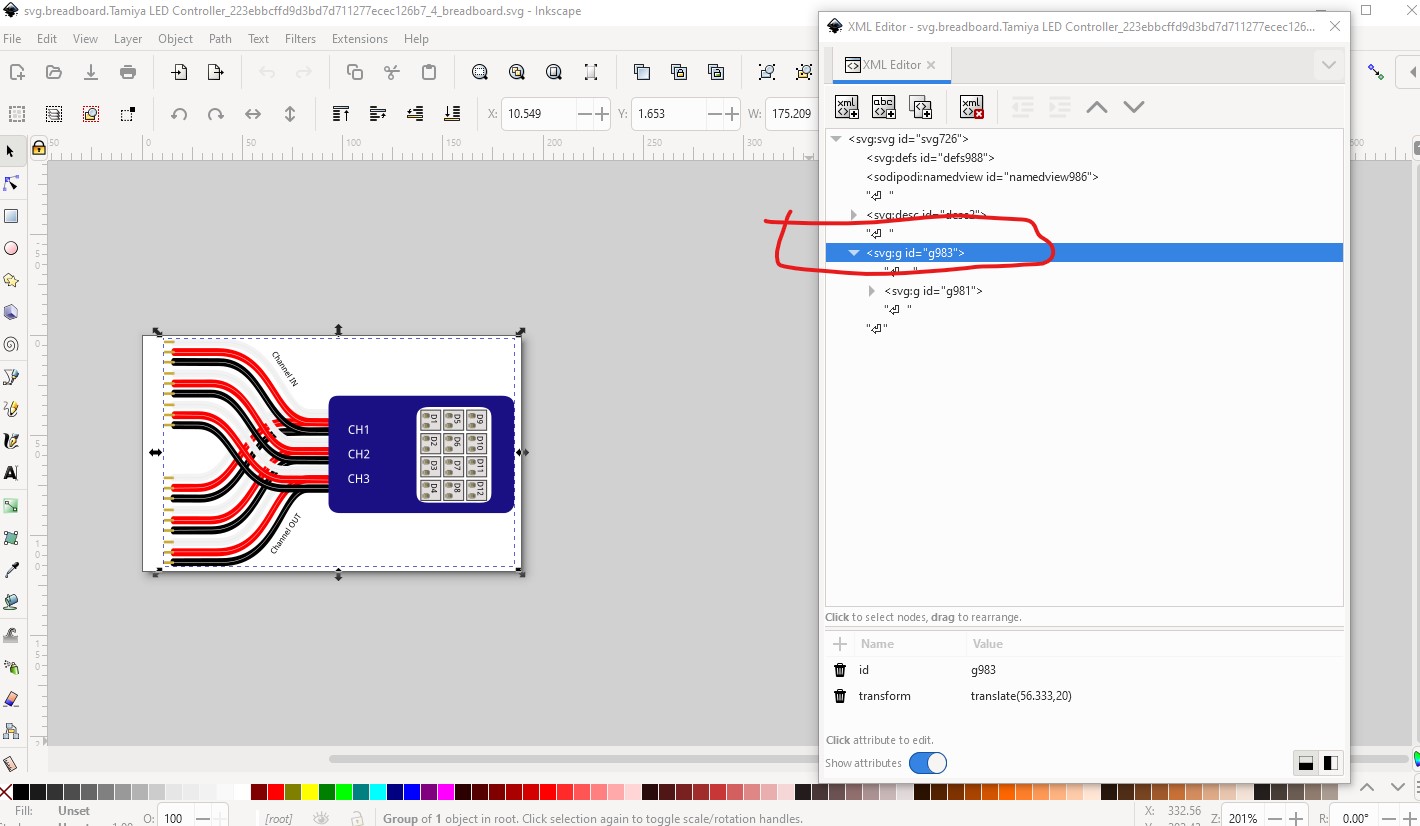
Found a drawing element before a layerId (or no layerId)
This is caused by there being no layerId group in the breadboard svg. The only thing I know of that this affects is that your part will not export as an image (svg, jpr, img, etc.) If is cured by grouping the entire image (which is done in this case)
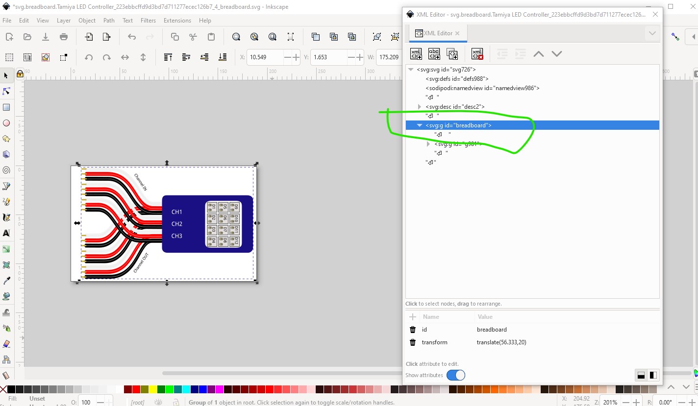
then naming the group breadboard (which needs to match the layerId in the .fzp file!) like this:
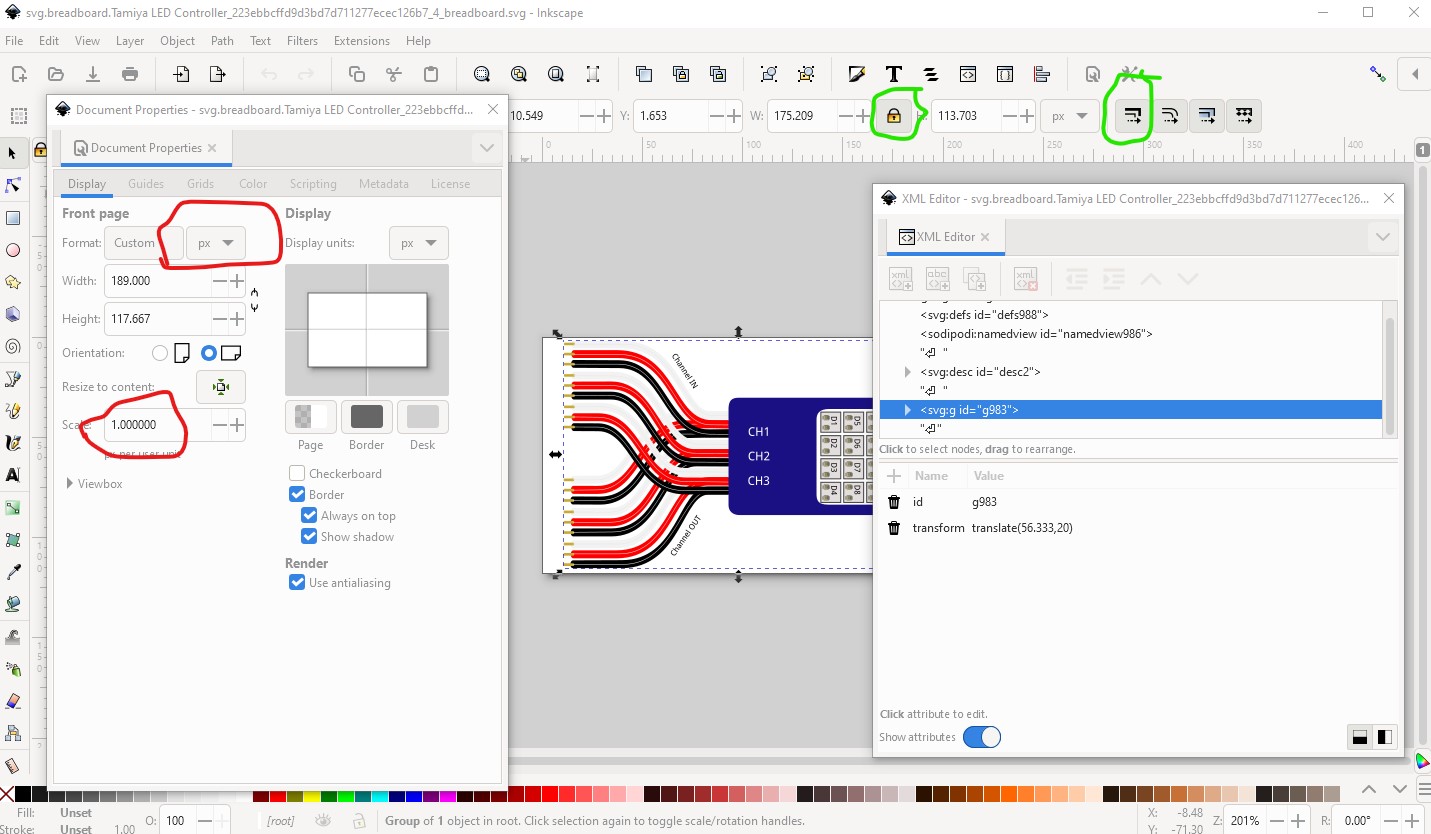
More of a problem (because you look to be using Illustrator rather than Inkscape as I am) is that the drawing is dimensioned in px causing this error:
Warning 19: File
‘svg.breadboard.Tamiya LED Controller_223ebbcffd9d3bd7d711277ecec126b7_4_breadboard.svg.bak’
At line 13
Height 117.667 is defined in px
in or mm is a better option (px can cause scaling problems!)
Warning 19: File
‘svg.breadboard.Tamiya LED Controller_223ebbcffd9d3bd7d711277ecec126b7_4_breadboard.svg.bak’
At line 13
Width 189 is defined in px
in or mm is a better option (px can cause scaling problems!)
the problem is that px is dependent on the DPI setting and Fritzing will guess at which of 72DPI (original Illustrator) or 90DPI (earlier svg standard) when the svg may be 96DPI (current svg standard.) If the dimensions are changed to in or mm (i.e. real world values) Fritzing won’t guess and the scale won’t be incorrect. This may be why your wires don’t match the grid in breadboard (or may not!) The problem is I don’t know if you can change this in Illustrator. Reading their documentation I have not found a way to modify the settings (they appear to think they know best how to set them, but in this particular case they are incorrect!) Hope this helps!
Peter
Thanks Peter,
I’ve been using both Illustrator & Inkscape to do the graphics, noted problem with scaling & using mm - So will have to go back & make sure its all the same ( in mm ) and get the spacing correct.
Sorry I’m not sure of how the internals look / work on the actual device as have yet to pull it apart. It could be pads or drilled holes - will report back when I have had look inside … ![]()
Had trouble finding data info on it, as it’s an Aliexpress item of Chinese origin :
So I’ve only done an ‘approximation’ just to get a basic part that could be used.
If you can find more info on the device - welcome to add to it here.
Will redo the schematic & add full cable nomenclature to the list, that should help with the doubling up errors.
Ciao, Bantum …
Ah, with the web site this makes more sense now (adding this url to the fzp file would be a good bet to tell others where to look!) I was looking at the Tamiya parts which are different! These get exciting as there is often not much info to go on. For the connectors in pcb I would go through hole, as if you connect it to a board it will probably be via the connectors in to headers rather then SMD. The breadboard svg is indeed in px (possibly via a change from Illustrator which appears to love px ![]() ) and as I recall so are schematic and pcb:
) and as I recall so are schematic and pcb:
for Fritzing it is desirable that the scale be 1 drawing unit = 1/1000in (although it doesn’t really affect anything other than meet the graphics standards) so assuming you are using Inkscape 1.2.2, as I am, with units set to in, the scale wants to be 0.001 (for mm it looks like it should be 0.025400) . If you lock width to height and set scale stroke width (both circled in green here) you can change the scale by modifying the width or height and circles will remain circles (with out being locked they usually change to ellipses due to fp round off.) There is a howto in tutorials on rescaling with Inkscape, but I haven’t updated it to match the latest Inkscape yet. Good luck (although having a part to check things on makes this much easier ![]() !)
!)
Peter
Also looking for a plug that I can attach to ends of the cable - something similar to this :

Have seen this : Servo connector (male and female)
Thinking of modifying to suit - as I need male / female ends in plan but … ![]()
Cheers, Bantum.
As noted in the referenced post we usually use headers for that, but it would be easy enough to make something like this in male and female or if you are making parts for the servo just add them to that part.
Peter