I have been trying to make just a schematic part work and cannot figure it out. It seems there is an issue where I screw up the grid alignments and then wires are not flat on the axis. I have tried a few templates in Inkscape and staring with a part and changing the image and every time the page size looks off on one axis or the connectors argue, etc. this can’t be this complicated!! When I dial in .1 inch spacing it does not seem to be the same as FZ. Maybe there are some new tips or resources I am missing? My goal is only schematics with new part connectors to play nice on the FZ grid.
What program are you using to edit the svg files? Inkscape is typical, Illustrator and others are possible. svg is based on xml, so a simple text editor works too.
From your description, I will guess that the 0.1 inch connector lines appear to be ‘off’ of the grid by 0.05 inch. That happens if terminal id elements are not included at the “snapable” end of each connector line, and included in the fzp file. Without the terminal id, Fritzing aligns the part to relative to the centre point of the connector line. “one” of the connector lines. It seems fairly random which connector is chosen for the reference point. To get full control of the alignment, every connector needs a terminal id, and they must all be positioned at multiples of 0.1 inch from each other.
The terminal id can be set in the fzp manually using a text editor, since it is another that is based on xml. Parts editor can set that up, but I edit the fzp directly, so am not current on how to do it with Parts Editor. @vanepp will probably chime in here with some tutorial references.
Another alignment problem possibility, is that the units are not set the way you think they are in the svg. Which was why the initial question about how you edit them.
Welcome aboard!
The most likely answer is a non obvious one: do you have a terminalId defined and is it on the end of the line that is the connector? For example if you only have this (just the pin):
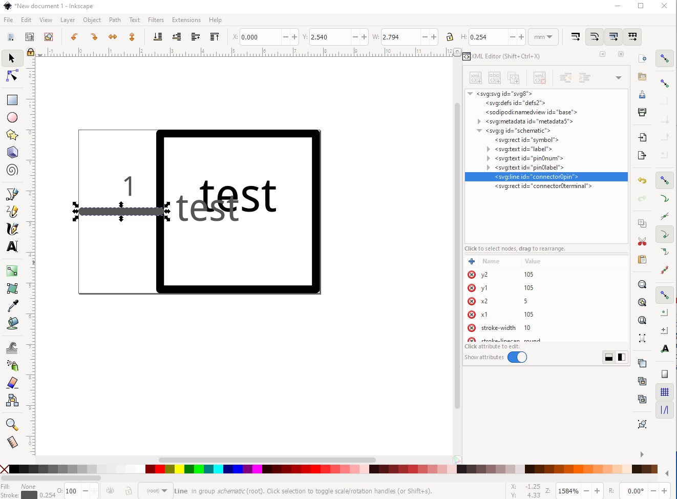
without this (the terminalId which tells Fritzing where the wire connects):

Fritzing will connect the wire in the center of the pin, then align the grid to the “terminal” (the center of the pin) and thus schematic will be offset 0.05in in x. With both the pin and terminalId set and correctly placed alignment will be correct. There is an Inkscape extension available here:
this is what I created the above example in. It creates correctly configured (correct scale, correct colors and terminalIds as long as you remember to tick the create terminalId box) schematic svgs. As well here are a couple of part making tutorials (and parts making is complex!) that apply to the current Fritzing versions (many of the rest are for older versions and may not be entirely correct anymore.)
Hope this helps, if not please upload the sketch that is not working (it will include your custom part as part of the sketch) and one of us will tell you what is wrong. Upload is 7th icon from the left in the reply menu and you want the .fzz file for the sketch.
Peter
Wow! Great help. I will try to absorb this… Yes, using Inkscape but I do not use the xml editor. I didn’t know there is a terminal id object-! That may be my problem but I was using the pins from a template that did work initially before I modded it and went back to FZ.
Another q I have is what is with the blue boxes when I go to assign pins? Sometimes I get random connections to the center of these objects in the schematic canvas! Also, I don’t understand the page size and its image appearing? Why do we need it?
It sounds like you are using parts editor (which I usually don’t as it is incomplete.) If you set the pins from there you can automatically set terminalId from here:
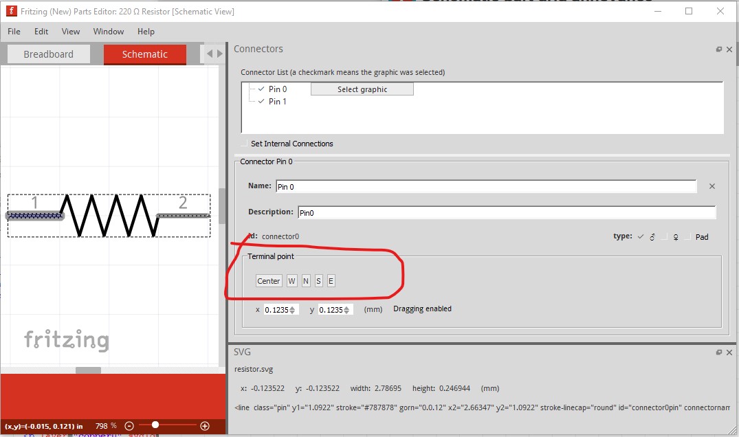
In this case I would want to use W (for west) I believe (although I have rarely been able to make this work, which is another reason I don’t use parts editor!) The default without a terminalId as noted is Center which is about the 1 in the middle of the line. There is a dangerous omission in my post, as well as the terminalId in the schematic svg you need a corresponding definition in the .fzp file associated with the part, if both are not present the terminalId won’t be recognized. In the fzp file this is correct:
     <schematicView>
      <p layer="schematic" svgId="connector0pin" terminalId="connector0terminal"/>
    </schematicView>
but this will exhibit the same problem (because the terminalId won’t be recognized):
    <schematicView>
      <p layer="schematic" svgId="connector0pin"/>
    </schematicView>
I don’t use parts editor enough to give a good answer to this, but it sounds like the pin hasn’t been defined (my usual problem!) correctly because the connector selection didn’t work. In such a case the wire will connect to the center of the part (usually with a red square indicating a connector definition problem) in the the views because Fritzing didn’t find a connector definition for a connector that is in the fzp file and uses the center of the part as the end point for the wire.
While I’m not entirely sure what this is, the last thing you should do after editing an svg in Inkscape is Edit->Select All then Edit->Resize page to selection. This sets the bounding box (which Fritzing uses to define the outline of the part) and the viewbox to match the image.Another common problem is having the units set to px like this:
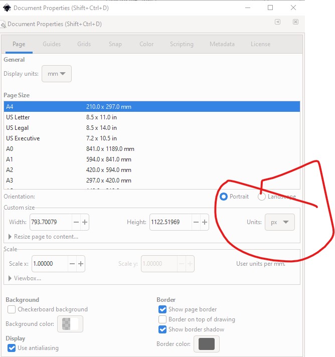
in Document Properties. Fritzing will then guess what the DPI value for px was (72DPI for older Illustrator, 90DPI for early Inkscape) when current Inkscape is 96DPI and then there are scaling problems in Fritzing (parts come out at the wrong scale and fail to align to the grid.) Setting the units to in or mm fixes this since an in is always an in like this:

Fritzing needs to know the size of the parts in real world units so the pcb gerber output can be in inches, which is the base of the reason Fritzing needs dimensions set in the svgs.
Peter
The same applies to all view. Fritzing needs to have some real world sizes, so that it can scale the graphics from different parts to get them to the same (relative) size in the view.
Something makes no sense to me. Here is my flow- I load template in Inkscape and save as. Then in another window I open my part svg that only has object “pins.” Then I select all the part an copy and paste it into the template. Then I move and group the new part svg so I can scale it and put it on top ove the previously working template part. Then I delete all extra pins, text and boxes I wont need. At this point I center my svg and size it to get nearest to the existing pins. Then, using select, I drag a group (but not grouped) pins using the coordinate box and line the edges best I can to the “page square” edge. Then I save as and open the parts editor in FZ. I load the new image. Then I assign the pins and the NSEOr W attribute. Then I save the part. Then I go to the Mine bin and drag the part out and usually one side aligns to the grid but never all of it works. I am using inches. I understand about if there are more pins and some remain unconnected, the square will be red. My problem is getting working pins that are connectable and stay on the grid vertically or horizontally as needed!
Probably the best bet is to upload the final svg (the forum often won’t render a valid svg in which case you need to zip the svg and rename it to .fzp and upload that telling us it is a zipped svg) from there I can probably tell you what is wrong. I’m not clear why you need to scale the svg (scaling usually causes problems because of floating point round off unless you lock height to width.) As noted problems like this are why I don’t use parts editor, but edit the underlying files directly. My procedure is detailed in the tutorial listed above.
This example uses the schematic template svg listed in the tutorial above.
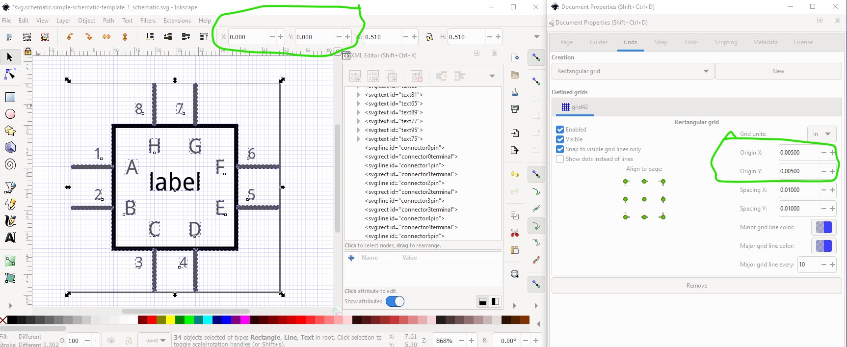
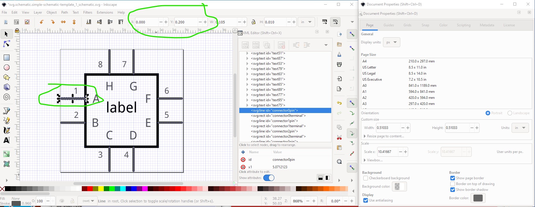
First make sure you have done Edit->select all then Edit->resize page to selection to insure that starting coords in the svg are 0 0 as in the image. Next note the .005in offset on the start of the grid on the Document Properties page on the right. The offset makes the grid lines (assuming stroke-width 10 lines) be the center of the lines. That in turn makes the positioning of pins easy to check, with dimensions set to in, they should be exactly on .1in boundaries as we see here:
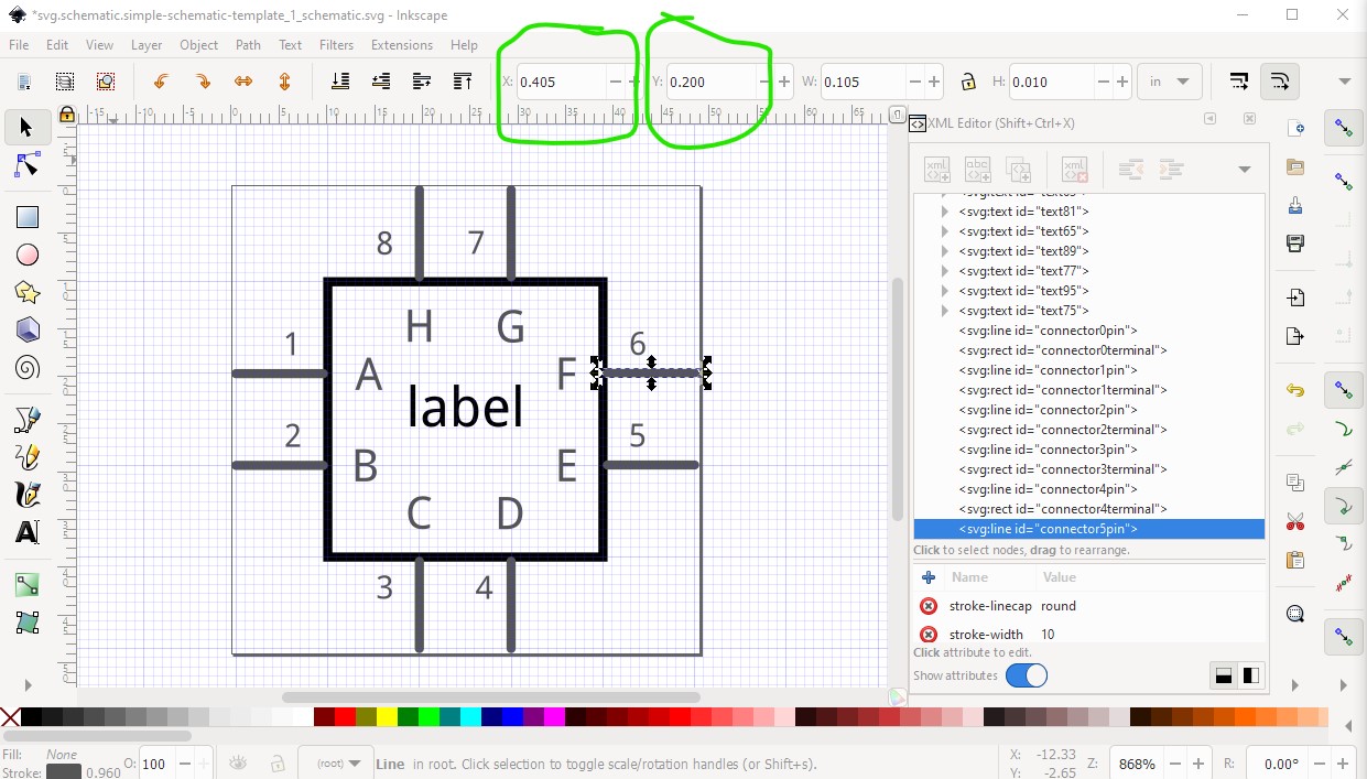
the other side will be offset by 0.05 in like this:
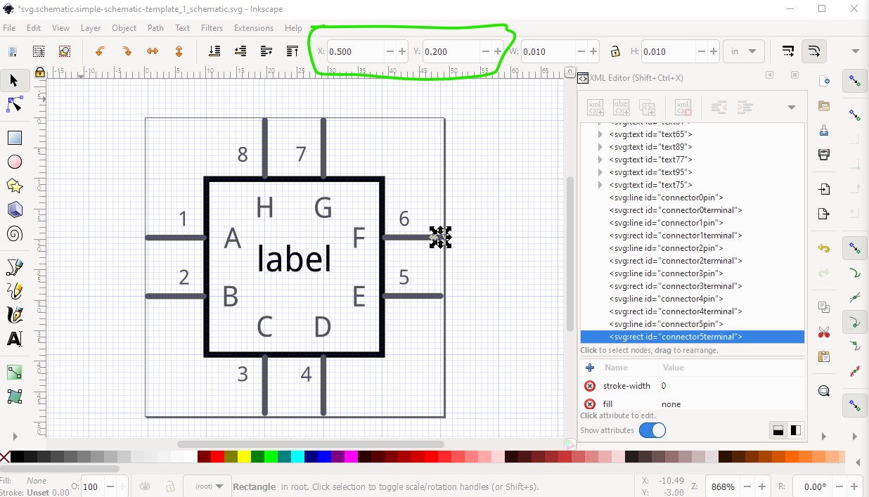
but the terminalIds (assuming 10thou by 10thou size!) are exactly on .1 boundaries, and the terminalId is what is used to align to the grid (if the terminalId is missing, the center of the pin will be used as the terminalId cause a 0.05in offset from the grid!)

and unlike the pin, the terminalId on the other side is exactly on .1in boundaries:
If you check all your pins after editing, they should be on .1 in boundaries. If they aren’t use the tool bar to move them to .1 boundaries and the grid should align.
Peter
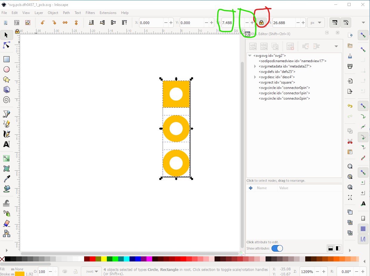
I need to scale the svg image because otherwise it is too large. It was not created for FZ, but I want to use it to avoid much new drawing. Thanks for the new flow checks. I will try them.
Ah! In that case set the width locked to height icon and use tool bar (either by setting a number in height or clicking the -/+ bars to change the scale.) If the two axis are not locked floating point roundoff tends to change the radius of circles to ellipses. With the lock set the circles stay circles (rather than become ellipses which mostly affects pcb.)
Peter