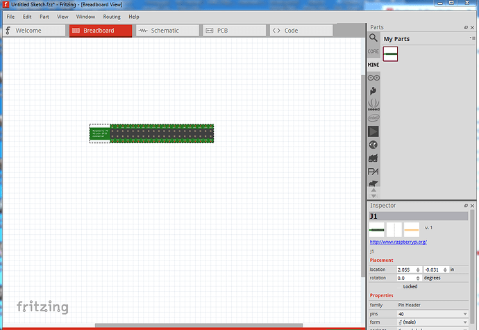
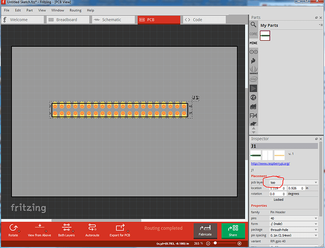
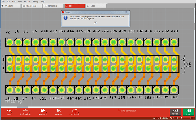
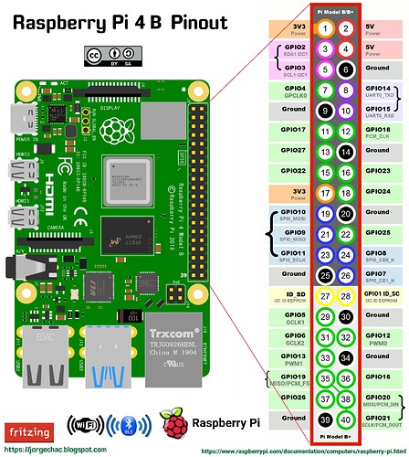
If you are creating your own Raspberry Pi shield, then having just 40 pin header with pin descriptions might help.
Raspberry Pi Header 40pin.fzpz (21.0 KB)
Gracias, en verdad me ha sido de gran ayuda 
Thanks for this!
Unfortunately though I’ve got an issue with it…
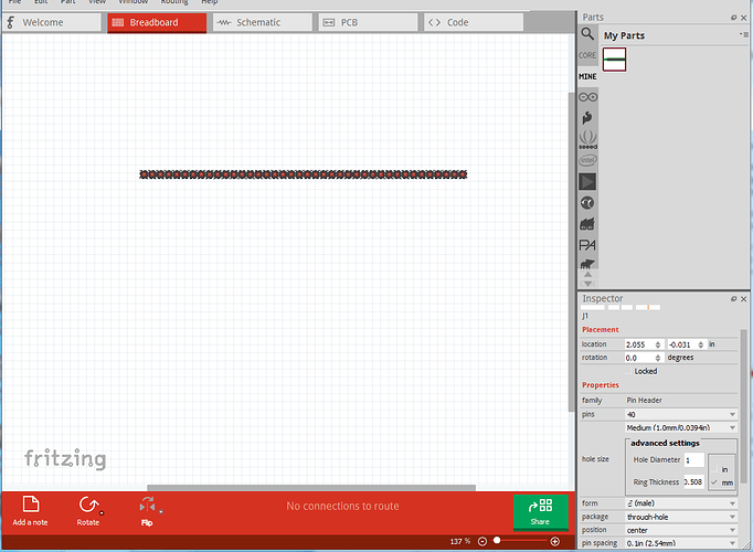
When I add it to my breadboard it’s perfect, but then I save my project, close Fritzing and then re-open the project and the header turns to being singled rowed instead of double rowed, any ideas on what’s going on there? I see the option ‘row’ and it is set to ‘double’ but this makes no difference compared to single, they both are a single row of 40, any help would be amazing!
Curious James.
Ah, correction, it’s when I play about with the part in the PCB view (i.e. move it between layers, and rotate and position it) that it makes the breadboard version (and NOT the PCB version) single rowed.
Thanks again, James.
Unfortunately you have likely hit a fritzing bug/feature (I was told some time ago that dual row headers in Fritzing breadboard should be single row, so I think this was originally intentional thus the “feature”.) I intend to fix the part factory at some point to correct that but haven’t gotten there yet. I expect what is happening is that when you make changes Fritzing is replacing the part with a generated one (Which will be in correct in breadboard.)
Peter
Here is an improved version of the Raspberry PI GPIO header for shields. The improvements are:
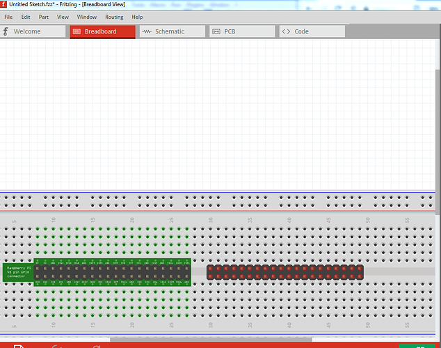
Breadboard:
Put the connector on an adapter board with a .4in pitch so it will connect in the center of the breadboard like this, and add pin labels:
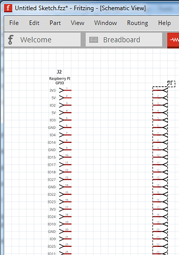
The new part is on the left and the original part on the right. You can not connect to the header pins directly in the new part, only via the connectors on the breadboard. Schematic has not changed a lot, only pin labels were added:
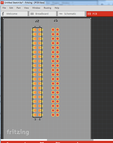
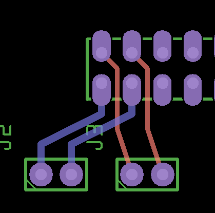
The direction of the connector was flipped (so input is on the right as is standard practice) and pin labels were added. The big change is in pcb. Because on a shield the GPIO connector is near the edge of the board the only routing choice is between the pins. With circular pads that is possible but not all that easy. So I changed the pads to be narrower oblong pads to allow easier routing between the pads:
Example gerber output with 4 connectors with traces (note to do this you need to reduce the pcb grid size from the default 0.1in to 0.05in and reduce the trace size from the default 24 mil to 16mil in Inspector for any trace going between pins. With those two changes the part passes default settings DRC):
and finally the new part then its test sketch (which has all 40 pins connected out one side:
edit: this part is broken if used on the bottom of the board, so I deleted it and replaced it with a part below in this thread that works correctly. If you have downloaded this part, please replace it with the new one below!
It is my intent to change the code of the part factory to have an option to generate this type of PCB footprint for both headers and ICs (as the function is useful for both) but I don’t have a time frame for completion (other than likely long  )
)
Peter
Hi Peter,
This is a great part that I will certainly make good use of, so thank you!
I’ve got that same bug though that when I set it to be on the bottom layer of the PCB layout (as would be needed when desigining a hat for the pi) it turns the breadboard component into a single row 40pin unlabelled header.
If needs be I could reverse my top and bottom on the PCB, so move everything else onto the ‘bottom’ and leave this on the ‘top’ and in reality they’d be the oposite.
Just a thought though on the pcb side - I assume the layer is defined as where you place your item, not where the solder pads will be, as the solder pads would need to be on the top, but the 40pin header will be on the bottom? I’m new to PCB design as I say, sorry.
Thanks again, James.
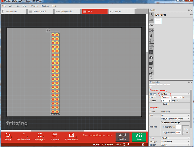
Well isn’t that ugly (and a bug)? I didn’t think to check the bottom of the board setting on the new part. When I did this:
turns in to this:
However the good news is that if I change the family from “pin header” to something else (which I will do right now) it should work normally as it will no longer interact with the parts factory code and do what you need.
Here is a new part with a different family name that works correctly in both views (until we manage to fix parts factory):
Raspberry-Pi-Header-40pin-new.fzpz (16.1 KB)
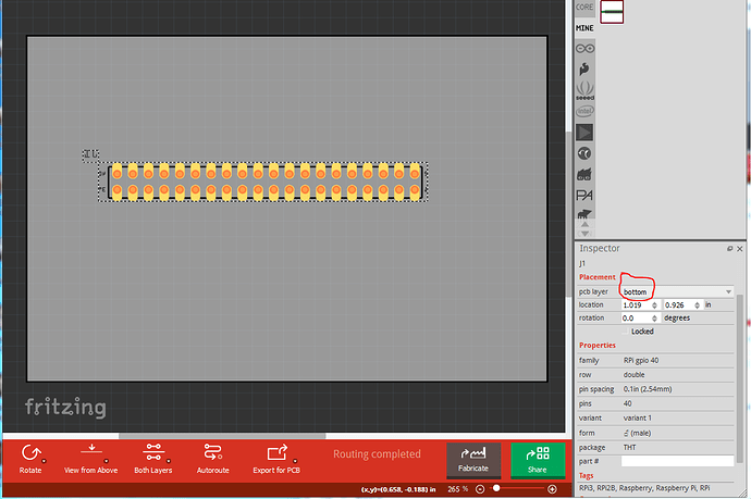
This is the main change, now when positioned on the bottom of the board the footprint reverses correctly (as the parts factory now longer recognizes it as a pin header and doesn’t change it!):
Good catch!
Peter
You’re a legend, thanks Peter!
Because development had stopped we had to be able to figure out workarounds when we ran in to problems because we couldn’t fix the problems in the source code. Now development is running again we can fix things like this (it is on my list, there are a variety of problems in parts factory) but it isn’t happening quickly so the workarounds are still valuable and this is an easy one, just change the family name to avoid the problem. A 2 line change in the part fzp file (as long as you know how to do it.)
Peter
Here is a new update for this part. The change is all in pcb, the pads are now smaller so you can stack these and run standard 24mil traces between pins and have it pass the default DRC rules.
and the new part. I have a set of boards using this layout coming, so I can make sure the pads work in practice. Assuming they do I will change the RPI-4B to use this and then add this as an option to the parts factory for making headers.
Raspberry-Pi-Header-40pin-improved.fzpz (14.8 KB)
I have left the original part (with longer thicker pads) available above as well so you can use the one that suits you best.
Peter
Hi @vanepp,
your Raspi header is really great! But i didn’t find any download link.
Would you perhaps mind to give me your part file?
Thanks in advance and greetings
Jochen
Edit: Thanks. Last post! Great.
The part download is the Raspberry-Pi-Header-40pin-improved.fzpz file in the post above. If you click on it, it will download the part file for the connector. There is an earlier version a few posts above. In Fritzing File->load->Raspberry-Pi-Header-40pin-improved.fzpz will load the part in to your mine parts bin.
Peter
I signed up to say thank you for this post ! 
Hallo.
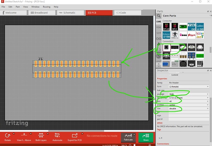
Iam looking for a SMD Variant of this Connector for the Raspberry Pi 4.
The first option is a generic header like this
If that doesn’t suit, then you would need to provide the data sheet of the connector you wish to use that includes a recommended pcb footprint.
Peter
That will work. Thank you.
