Is the TSR 1-2450 in the Parts Catalog?

I have not found that part available for Fritizing.

Has anyone used another/similar part with he same geometry that could be use to create PCB?

TSR 1-2450

Adafruit maintains their own fritzing parts repository although it doesn’t seem to be in there at a quick look. It is a trivial part to make though, so I can create one easily enough.

edit:
This should do what you want. As always check the footprint against a real part before ordering boards (preferably by printing the output from a gerber viewer to check as that is what will cut the board). As a bonus (although come to think of it, I didn’t tasg it that way) this is in perfboard format as opposed to standard breadboard.

edit2: Failed to resize page in the pcb svg truncating the silkscreen outline. Corrected, so if you have downloaded this part please download it again.

TSR12450.fzpz (5.5 KB)

Peter

Thank you very much!

Peter,

Can you point me in the direction as to how to add an outline on that in the PCB view?

I put the part on the project but in the PCB view there is no way to grab it to move or rotate it.

I could not figure out how to edit that?

John

My bad, I didn’t edit silkscreen. I don’t think you can do it from within Fritzing, you need to use an svg editer (I use Inkscape) and edit the svg. If you want to learn parts making there are a series of videos, but it has a steep learning curve (depending on where you start). For me with no knowledge of Fritzing or svg editing it was around a year. Mant if the tutorials around are for older versions of Fritzing, these two are for the current version:

meanwhile I’ll add a proper outline to the pcb svg and upload a new version.

Edit:

Easier than I thought. The outline was there, I just failed to resize the svg, so it was outside the view box and thus truncated. If you download the part again you should now have a proper silkscreen outline.

Peter

Thank you very much. It is very helpful.

Heya, I know this is an old thread but I wondered if you could help please.

I’m very new to Fritzing let alone PCB design, so I’m sorry if this is dumb…

For some reason this component seems to bridge GND and V Out, of course I could have a bridge else where on the board, but I don’t believe that’s the case, I’ve not noticed that until now at any rate.

So is the component’s schema wrong perhaps?

Thanks, James.

The only dumb question is the one you don’t ask :slight_smile: all of us had to learn at some point. It sounds like you may have hit a Fritizing bug/feature (I’m not yet sure that it isn’t a case of some actions can’t be recovered rather than a bug.) If you make an incorrect change in another view (i.e. connect a wire in breadboard that is connected to something different in schematic) it is possible to corrupt the sketch so it won’t recover even if the error is removed. The best bet is if you can upload the sketch (the .fzz file) via the 7th icon from the left on the reply menu. I’ll have a look at the sketch and tell you whats wrong with it.

Peter

Door Pi.fzz (77.1 KB)

Thanks Peter you are a hero, that’s two bugs I’ve potentially hit now, I’m feeling pretty unlucky lol.

James.

This seems more incorrect connections than the bug/feature. In pcb you have two shorts between 5V and ground (and the dc dc inverter is incorrect as well!) The first one is here on the RPI connector:

Capture

The yellow (top side) trace connects 5V to GND on the connector. Same on the DC-DC converter:

the brown (bottom trace) is shorting 5V to GND. After that, the DC-DC converter is incorrect in that it takes an input from 6 to 12V on Input (which is currently fed from 5V) and produces 5V on the output. It looks like the DC-DC converter should connect to the barrel connector, but it doesn’t seem to and the 5V output from the DC-DC converter can’t connect to the 5V supply on the RPI because it would be a conflict. Hope this helps.

Peter

I could be wrong, but I can’t get on it right now to confirm - but I believe the 40-pin PCB line was auto-traced, and the tsr1 definately was.

This may well be due to an error on my breadboard where the PCB design comes from, though I’ve not found where myself.

James.

Ah, that would indicate problems in breadboard. Is the intent to power the PI from the barrel jack (i.e. that is the source of 6 to12V that should be the input to the DC/DC converter and then power the PI? Part of my problem is not knowing what should connect to what. I’ll have a look at breadboard and see if I can see something (probably by deleting all routing in pcb and going from there.)

Peter

So the TSR1 is dropping down the 12v input (on the barrel) to 5v for the 5v rails, which indeed powers the pi via the header pins.

So do you do it from the PCB and that generates the Breadboard then? or is that just one directional?

Also I’ve updated it a bit (attached).

Lastly I’ve got that 40pin header on the PCB but it’s not on the breadboard any more, I’ve no idea how that’s happened.

James.
Door Pi.fzz (78.2 KB)

I saw that. Another bug. The breadboard should be the lowest item and all parts above it, but in this case that isn’t happening. To fix it, right click on the breadboard and select Raise and lower->Send to Back which should put the breadboard on the bottom and make the connector reappear (it is just hidden, not missing as it appears.) Your power leds all need a series current limiting resistor , connected as they are the 12V and 5V ones will burn out and the 3.3V do nothing (because it doesn’t have a ground.) You are doing something odd in PCB because if in PCB I do a “Routing->Select all traces” and then hit delete (which deletes all the traces) then run autoroute I get a mostly correct layout (two wires can’t be routed due to clearances) that doesn’t match your original.

original:

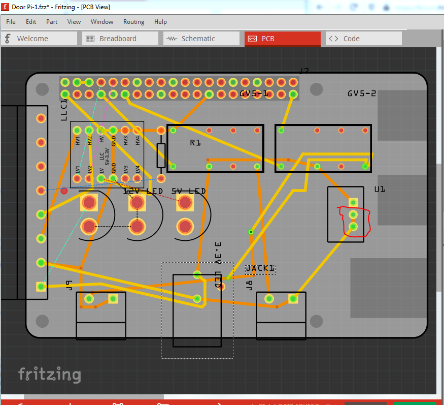
red circle indicates a short between power and ground.

traces deleted leaving only the rats nest lines:

Autorouted:

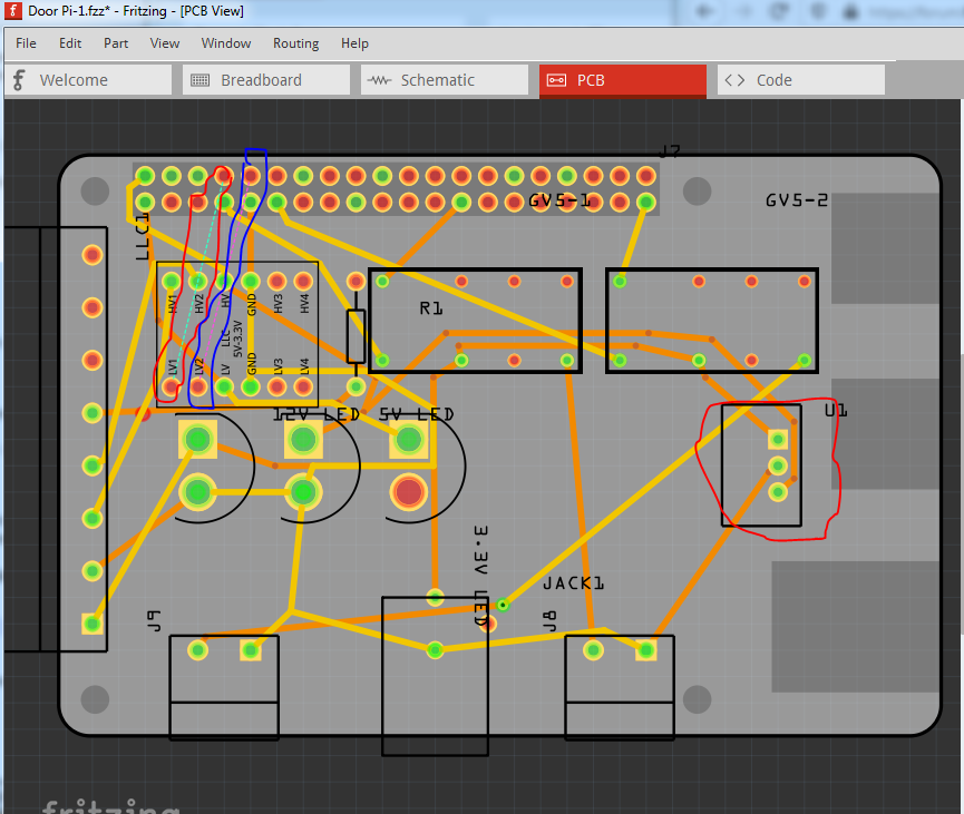
note the difference in the traces on the dc dc converter. The two unroutable traces are outlined in red and blue at the top left. They can be manually routed by reducing the trace size and being creative, but that should wait til the design is complete. Note the 3.3V led has no connection to one of its pins so won’t do anything (and the labels should be dragged to be on the correct LED, the 12V is currently on the 5V led) and as noted the all three need current limiting resistors. Once we get a complete circuit I’ll clean up the autorouting to make the layout better. Except for very simple layouts autorouting is usually not useful ( a manual route is much much better.)

Edit: I just realized there are another two problems here: there are no supressor diodes on the relay coils and there are no relay drivers. The relay coil takes 100ma to operate according to the data sheet and a Raspberry PI output pin can only sink about 16Ma (much less than the 100ma the relay wants) and thus you will need a relay driver for the two coils. A simple transistor circuit with a snubber diode would probably be easiest, or a ULN2003 7 channel driver (of which you only need 2) as it already has the snubber diodes in it.

Edit: You probably want to pick up my just posted improved GPIO header part from here:

as it will make routing the pcb easier.

Peter

Firstly thanks so very much for putting so much time into helping me with this Peter, that’s very kind of you and I really appreciate it!

On my (non-identical) breadboard everything is working, so I’ve got an idea of what is electronically working OK, but the exact position of pins isn’t identical, that said I don’t know best procedures so for example I’m not sure what ‘supressor diodes’ are, I found with those DC DC relays I made a couple mistakes; firstly they’re 5v and the Pi GPIO is 3.3v, and secondly they need a rather high current from that 3.3v like you say, so I instead found the 3v High sensativity version (G5V2H13DC) which I’ve tested works fine when two are being driven by the GPIO from the Pi, however if you’ve got a best practice I should still implement for them I’m all ears, as even the high sensativity ones claim they draw 50ma, so they technically shouldn’t work, but do.

As for the LEDs, I didn’t know what resistors to use to drop them down from 12v,5v, or even 3.3v so I ordered ones that had built in resistors for those voltages, if you’d be able to advise me on what resistors to use for that I’d be very happy to hear it, as I want to drop the idea of individual ones and instead move to two indicator LEDs like these: https://uk.rs-online.com/web/p/pcb-led-indicators/6164071/ as I can then fit more on the PCB without taking so much space. My plan is to have two of those, the red ones would be for the two relay outputs (in parallel to the relay outputs so that they are indicators as to whether those Relays are outputting), and then the green ones would be used to show 12v power is coming in OK, and that 3.3v power is OK (a cheap way I can think of to show the Pi is on).

While we’re here, can you confirm how wide the trace should be for 12V 0.8A as that’s what one of the relays will be driving (a clanging doorbell).

I didn’t know you could delete the PCB traces like that, but I’ve done that now and it too has cleared up those bridges, so thanks very much!

James.

As for the one resistor coming off the GPIO pin on the current design that’s there because the LED of the keypard/RFID reader I’m connecting to changes state when I set the GPIO to low, but I’ve found that if the Pi is off then the GPIO is essentially ground anyway, such that the LED changes when the Pi is off, which isn’t something I want to happen, so I found by experiment that putting a resistor there means it doesn’t change state (to green) when the Pi is off, but does change to green when the Pi sets the GPIO pin to low, if that’s a good or bad implementation I have no idea, I can only assume there’s a better way, so if that’s the case again I’d love to know it if you’re happy to tell me.

Thanks again!

I’m lucky enough to be retired and well off, with time on my hands. I also have 50+ years of other folks teaching me things to pay forward to new generations :slight_smile: and posting here helps lots of other folks that read this as well.

The issue on snubber diodes is that a relay coil is an inductor, and when it shuts off it will raise the voltage (from stored energy in the magnetic field) in an attempt to keep the current constant. It can raise the voltage much higher (for a very brief time due to lack of energy) than the 3.3 or 5V driving it and that can damage the PI I/O pins. If you have room on the board for an additional 16pin IC I would suggest using a ULN2003A driver. It should run fine from a 3.3V input (and take almost no current from the PI I/O pin) and already has the appropriate diode across its output transistor to deal with an inductive load. I think they are capable of about .5A per driver so they have lots for what you need. You only need 2 of the 7 drivers, but it is safe to leave the unused drivers unconnected (this isn’t safe with CMOS ICs, but the 2003A isn’t CMOS.) The in pin goes to the PI port and corresponding Out pin goes to the relay coil. The ULN2003A is on core parts. That way if something bad happens the cheap 2003A burns out not the expensive PI :slight_smile: . Current limiting resistors for the leds are fairly easy. The data sheet for the LEDs indicates they are fairly standard, and want about 20Ma of current and have a forward voltage around 2V (it is slightly higher for the green one, but that doesn’t matter.) To calculate the value of the resistor we use ohms law:

R =E/I where I is current, E is voltage and R is resistance. Here we know the desired current (15Ma) and the voltages
12V, 5V, 3.3V with one slight twist in that we have a 2V forward voltage on the diode, so the voltage across the resistor (to calculate the current) will be 2V less so 10V, 3V and 1.3V. So the 12V LED we use the R = E/I form of ohms law to calculate a resistance then convert it to a standard value like this. I cheated and used a web based calculator because I’m too lazy to do the math. The calculator is here:

scroll down the page a bit and enter these values:

Voltage source enter 12 (Volts)
Voltage drop from LED enter 2 (Volts)
Current through LED enter 15 (Ma)

then hit calculate and it comes up with

666.66667 ohms as the resistor value. A 680 ohm resistor is the closest standard value, so use that (it only needs to be approximate, a little more or less current won’t hurt anything)

5V wants a 200 ohm resistor, so use a 220 ohm standard value (the value selector in Fritzing’s inspector will give you the standard resistor values.)

3.3V wants 86 ohms, so use a standard 82 ohm resistor.

Again, be lazy and cheat :slight_smile: , there are calculators on the web for PCB trace width against current, a google search for “pcb trace width calculator” turns up a bunch. I used the digikey one (because I like digikey :slight_smile: ) at:

https://www.digikey.com/en/resources/conversion-calculators/conversion-calculator-pcb-trace-width

Current is .8 (Amps)
Thickness 1 (Oz/sg ft) 1 ounce copper is a common value
Temperature Rise 10 (10 degrees above ambient is only 32
Ambient Temperature 22 (normal house temp)
Trace length .5 (Inch)

Tells me the trace width should be 22 mils so a standard 24 mil trace should be fine. It will get larger with more trace length, or more current, but .5 in seems a reasonable value here.

Do you have a pointer to the data sheet for the keypad/RFID reader? The likely answer here is that the RFID reader needs a pull up resistor to its 3.3V supply on the pin that the PI is driving. An I/O pin has two legal states and one illegal state, using a 3.3V I/O pin as an example a high level is likely to be considered 2.2V to 3.3V and a low state from 0 to .7V, that leaves the range from .7V to 2.2V as the indeterminate state. If the I/O pin voltage is in that range, the input may read as 0 or 1 (or alternate between them randomly). What your resistor is likely doing is raising the voltage on the pin of the RFID reader to more than 2.2V (or at least high enough to be usually read as a 1) when the PI is powered down, so the RFID reader sees a high level and doesn’t trigger. The usual way to deal with this would be to put a resistor between the RFID I/O pin and the 3.3V power supply on the RFID reader so as long as the RFID reader has power, the input pin is pulled high until the PI pulls it low. A value around 1K ohm should do (the PI I/O pin needs to be able to sink the current through the 1K resistor which will be about 3.3Ma when the PI drives the pin low, which is what sets the resistor value.) The series resistor that is present currently may only be getting the input high enough to usually show as high on the RFID reader and thus may in some instances not work correctly if conditions are just right. Hope this helps somewhat, you are in a tough area here :slight_smile: insuring a stable state during power up is tricky usually.

Peter