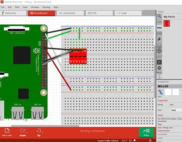
My first hint is to clean up breadboard. If you are intending to actually breadboard this first, cleaning up will make that easier. Here is a partial reproduction of your breadboard
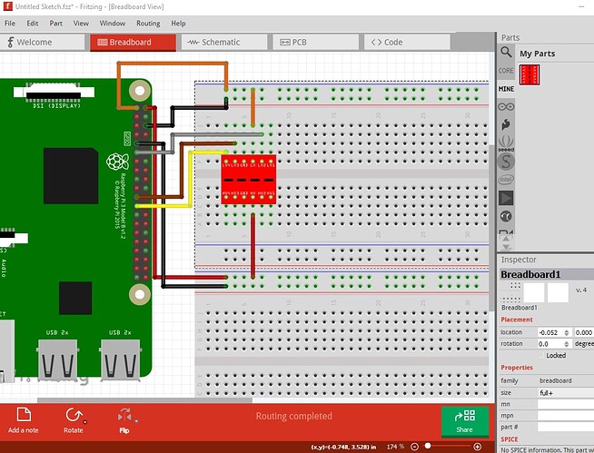
followed by how I would change it
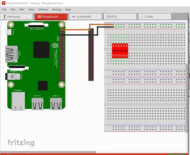
Here the 3.3V wires are all orange (so you can see at a glance where 3.3V, 5V and GND are) they connect in an organized fashion to the breadboard and connect to an open pin on the breadboard (not directly to the part which works in Fritzing but won’t in real life!) 5V is red GND is black and the signal wires should be different colors to make it obvious where a connection goes. Now on to your actual question about a GPIO cable. There isn’t an easy way in Fritzing to make such a cable, in breadboard individual wires (routed sensibly!) will do. Assuming the breakout boards will all connect to the pcb (the ones here all should) then what I would suggest is use two 20 pin headers to duplicate the GPIO connector (or better yet use this part which will allow you to route traces between pins in pcb which a standard header will not!)
It works like this (with only two wires done)
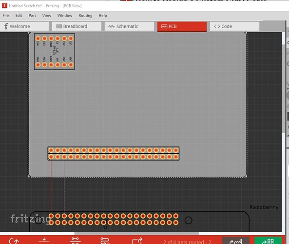
which in pcb looks like this
with the Raspberry PI outside the gray pcb area it will not appear on the pcb but will connect in breadboard and schematic. The Raspberry PI then connects via a 40pin IDC ribbon cable to the headers on the pcb. Alternately you can make your board in to a Hat which will plug directly in to the GPIO connector (again I would use the above header part rather than a standard header.) Hope this helps.
Peter


