P82B715.fzpz (6.5 KB)
I ran that part through I ran that part file through GitHub - fritzing/FritzingCheckPart. It reports some cosmetic issues, but the important problem, is the schematic svg file. It does not have the “schematic” layer. The complete graphics needs to be wrapped in a group that has an id of “schematic”.
The other problem is that all of the connector«n»terminal elements are groups (g elements). That does not work. They need to be ‘real’ graphics. Usually a rect element.
Extract from the FritzingCheckPart report below
$ FritzingCheckPart part.P82B715_52ca0bb982cddce0aa9b7391cc874c5b_1.fzp

Modified 1: File
'…/svg.breadboard.P82B715_e1442170b3233e2165be3696c4b47d5c_5_breadboard.svg.bak'
At line 18

Removed px from font-size leaving 5.55556

Modified 1: File
'…/svg.breadboard.P82B715_e1442170b3233e2165be3696c4b47d5c_5_breadboard.svg.bak'
At line 19

Removed px from font-size leaving 5.55556

Modified 3: File
'…/svg.pcb.P82B715_e1442170b3233e2165be3696c4b47d5c_5_pcb.svg.bak'
At line 8

Silkscreen, converted stroke from white to black

…
Warning 7: File
'…/part.P82B715_52ca0bb982cddce0aa9b7391cc874c5b_1.fzp.bak'
At line 2

No Fritzing version in fzp file


Error 69: File
'…/svg.schematic.P82B715_e1442170b3233e2165be3696c4b47d5c_5_schematic.svg.bak'
At line 8

Found a drawing element before a layerId (or no layerId)

Error 77: File
'…/svg.schematic.P82B715_e1442170b3233e2165be3696c4b47d5c_5_schematic.svg.bak'
At line 12

terminalId connector0terminal can't be a g as it won't work.
…
- could some one say, how to clean fzpz from garbage like svg.bak ? don’t know how to do that.
- and could some one leave here link of correct decor part (maybe, I’ll try to bring it to a similar state)
microMerlin, thanks for your attention!
p.s. wrong templates in fritzing born new wrong parts… is it?
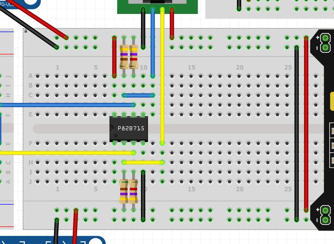
at breadboard looks fine :)))
svg.bak isn’t garbage, but rather the original svg where the referenced line numbers are correct (because the output svg has been modified and pretty printed, probably changing the line numbers.) That said the second tutorial set describes how to make the modifications (I don’t usually use parts editor but edit the underlying files directly which is what you need to do to use FritzingCheckPart.)
schematic Incscape plugin (which makes correct schematics more easily in Inkscape although it has some limitations)
It is more correct to say the templates are outdated. They don’t meet the current graphics standards. As well the parts factory is also old and emits parts that don’t meet the current graphics standards and haven’t been updated yet (because the updates are complex!) There typically isn’t a lot of interest (including by me ![]() ) in updating the documentation, most effort is going in to code changes at the moment (there was a 4 year pause in development which has created problems!)
) in updating the documentation, most effort is going in to code changes at the moment (there was a 4 year pause in development which has created problems!)
Peter
vanepp, thanks for the tutorial links.
p.s. I also edited separate parts of breadboard, icon, pcb and schematic in inkscape.
apparently the chosen basic template from fritzing was not successful, and I didn’t want to spend a lot of time, that’s the result.