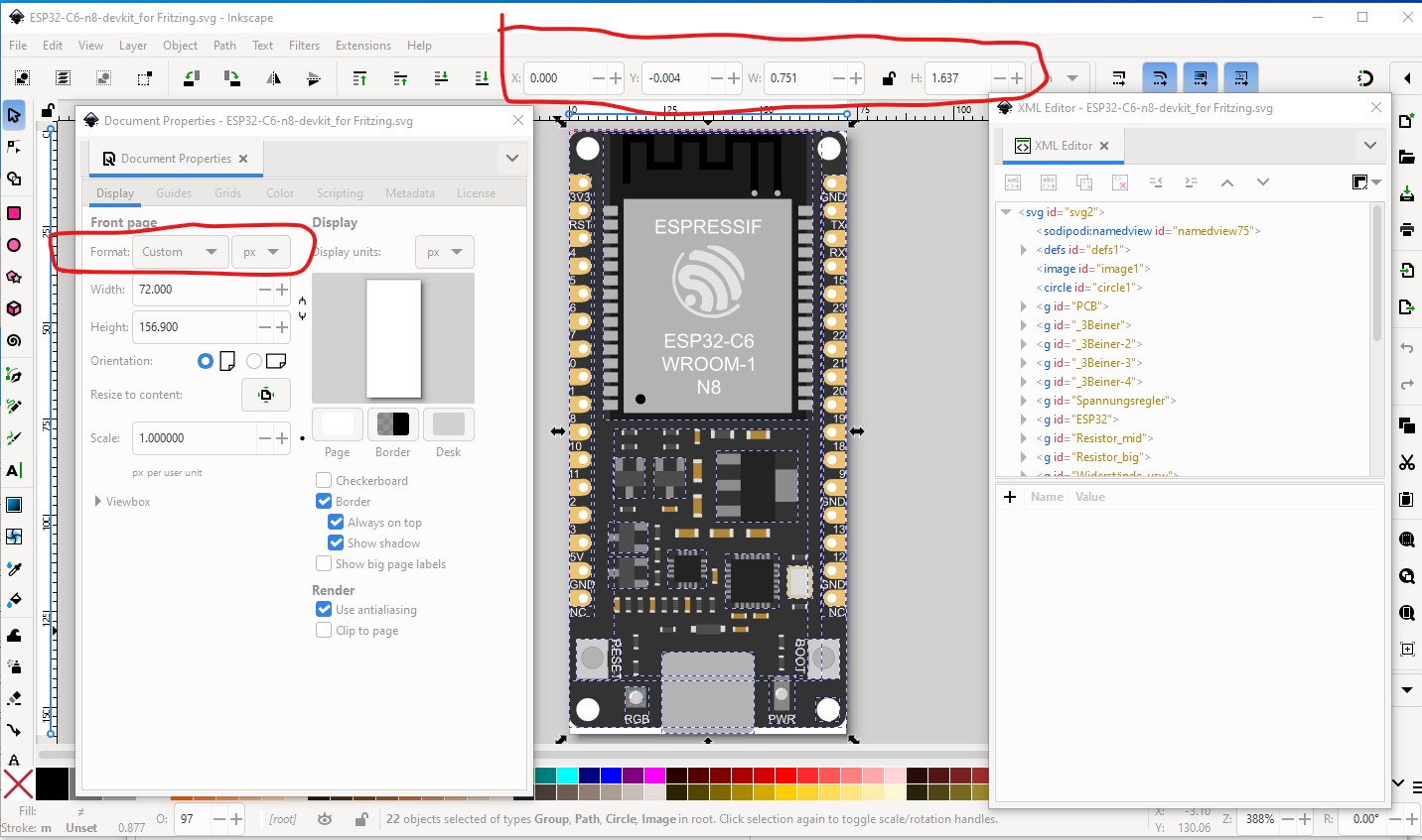
Illustrator is probably a bad choice for Fritizng. Inkscape is preferred. Your svg has a number of problems. The connectors are not correctly defined, and the dimensions are in px which will likely cause scaling problems. Other folks that make parts use Illustrator so it is possible I just have not been able to figure out how from their documentation (I don’t have Illustrator to try it on either) they don’t appear to think you need control of the svg as far as I can see. For Fritzing they are incorrect. Your fonts are also wrong. Fritzing will only accept OCRA and Droid Sans, anything else (your svg is using arial) will be substituted to one of the accepted fonts (with variable results usually!)
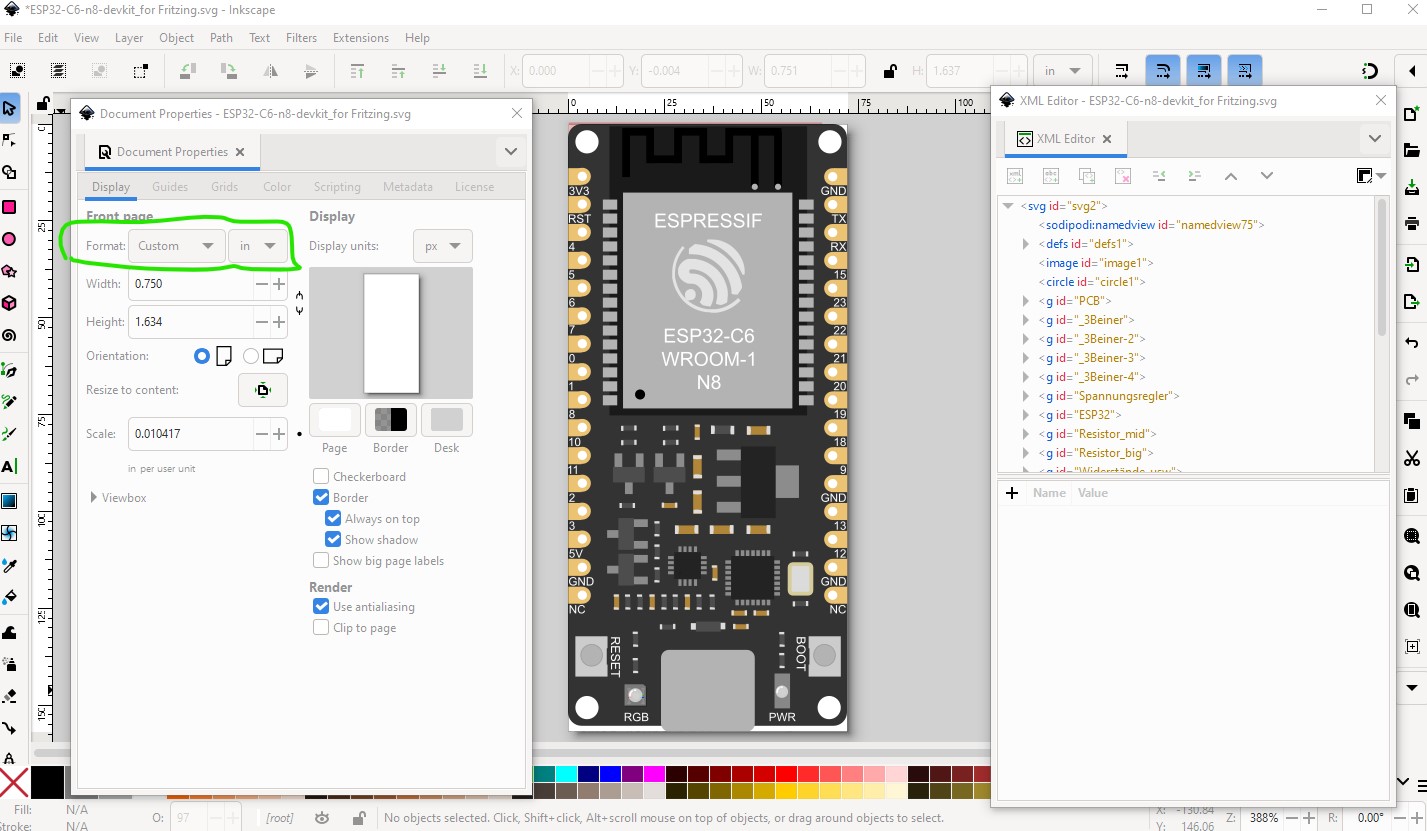
Here I changed dimensions to in, but the scale is almost certainly wrong because the space in y between 2 pins should be 0.1in to be correct but it is not.
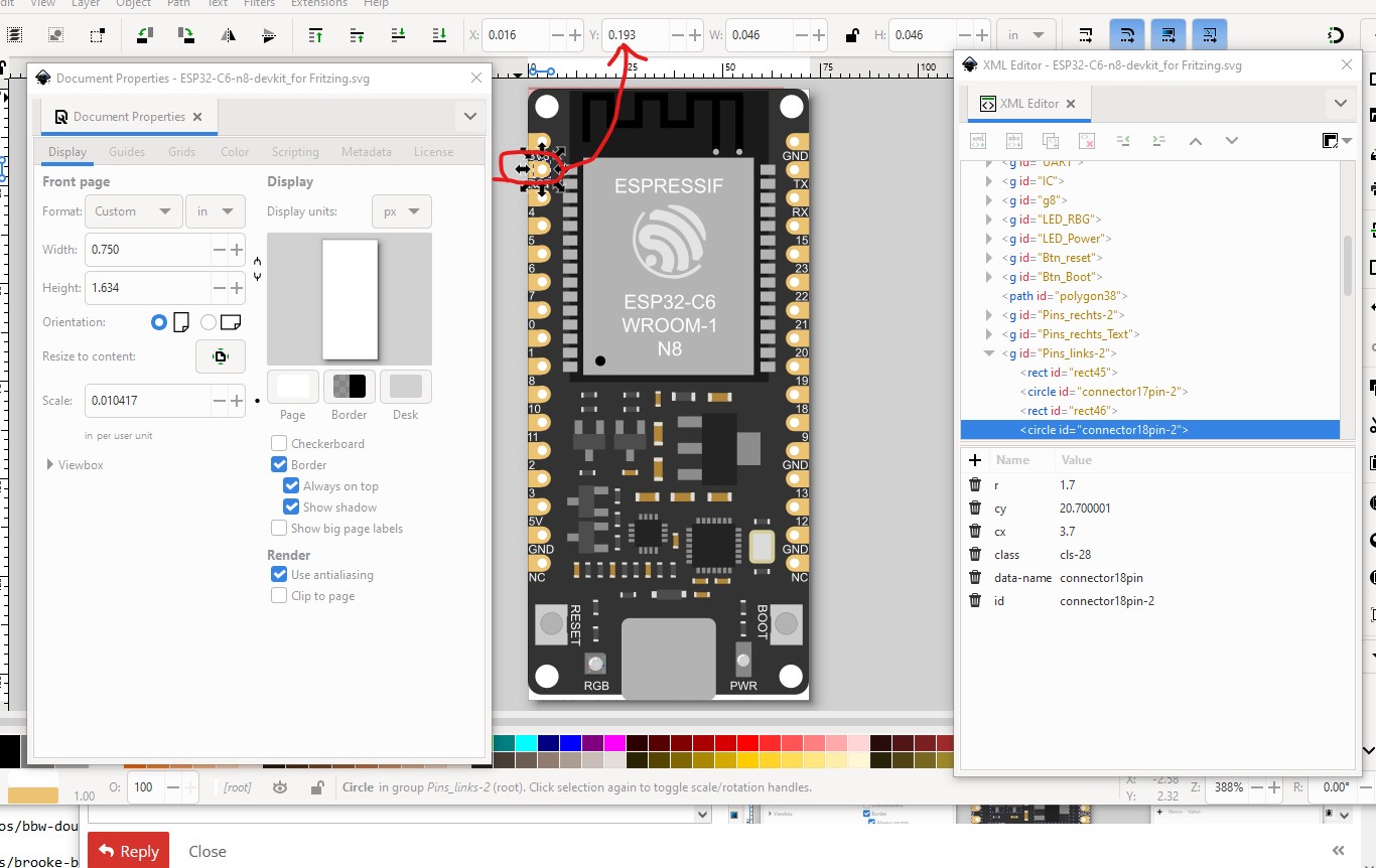
The first pin is at 0118 in so the second should be at 0.218in
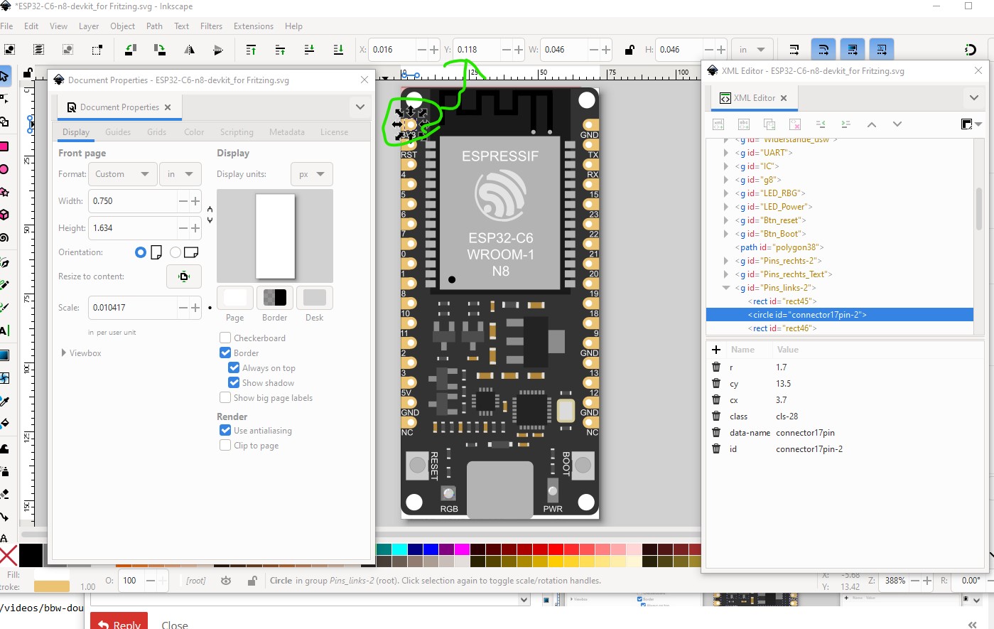
but it is not. It is at 0.193in (too short.)
That said these two tutorials will tell you what you need to do to make parts (old_grey’s covers the parts editor which I don’t use.)
I lately learned there aren’t links to the videos in Old_Grey’s tutorial so you need to do a google search for the title and then they come up on YouTube.
For parts editor you need an existing part with 30 pins to modify the svgs and fzp file for to make a new part. Parts editor (AFAIK) can not modify most of the fzp file so it needs to be mostly correct before you start. I tend to just edit the files directly and ignore parts editor, but I have a lot of experience at making parts. There are a couple of 30 pin ESP boards around such as this one
that would serve as a base to make a part.
Peter