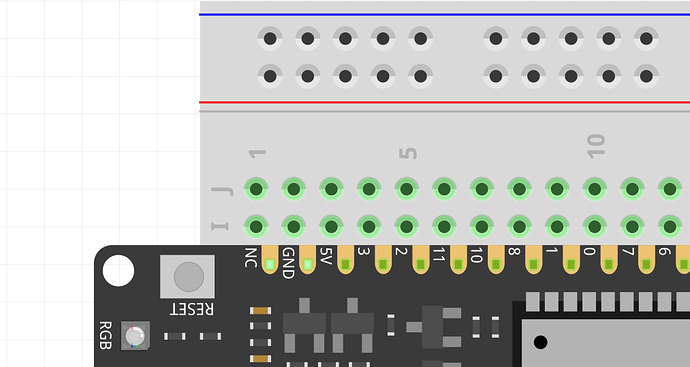
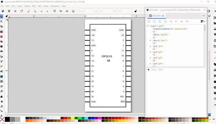
I could not find it, so I created a drawing for ESP32-C6-N8 Waveshare. Can you please help me to import the part into Fritzing parts editor and maybe to finish it? Cannot open it in the parts editor. If you like feel free to include it to your library.
Any help appreciated !!
Many thanks.
Here is an SVG and an Illustrator file: SwissTransfer - Envoi sécurisé et gratuit de gros fichiers
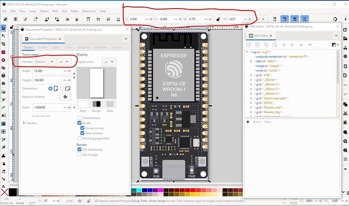
Illustrator is probably a bad choice for Fritizng. Inkscape is preferred. Your svg has a number of problems. The connectors are not correctly defined, and the dimensions are in px which will likely cause scaling problems. Other folks that make parts use Illustrator so it is possible I just have not been able to figure out how from their documentation (I don’t have Illustrator to try it on either) they don’t appear to think you need control of the svg as far as I can see. For Fritzing they are incorrect. Your fonts are also wrong. Fritzing will only accept OCRA and Droid Sans, anything else (your svg is using arial) will be substituted to one of the accepted fonts (with variable results usually!)
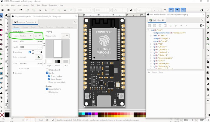
Here I changed dimensions to in, but the scale is almost certainly wrong because the space in y between 2 pins should be 0.1in to be correct but it is not.
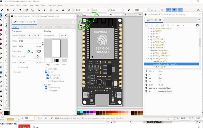
The first pin is at 0118 in so the second should be at 0.218in
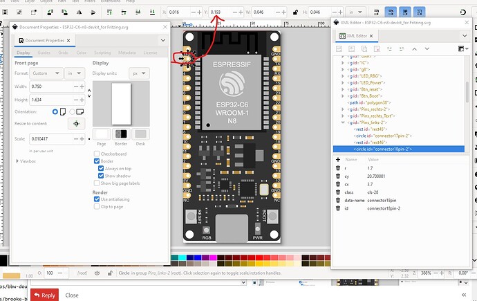
but it is not. It is at 0.193in (too short.)
That said these two tutorials will tell you what you need to do to make parts (old_grey’s covers the parts editor which I don’t use.)
I lately learned there aren’t links to the videos in Old_Grey’s tutorial so you need to do a google search for the title and then they come up on YouTube.
For parts editor you need an existing part with 30 pins to modify the svgs and fzp file for to make a new part. Parts editor (AFAIK) can not modify most of the fzp file so it needs to be mostly correct before you start. I tend to just edit the files directly and ignore parts editor, but I have a lot of experience at making parts. There are a couple of 30 pin ESP boards around such as this one
that would serve as a base to make a part.
Peter
Ciao Peter
Thanks for your message. Finally I got it working - I continued on Inkscape. No idea, why the measurements we broken. I used another part for designing my part…
Feel free to add this part to your public repo in case anyone needs it.
ESP32-C6-N8.fzpz (72.9 KB)
Best, Jan
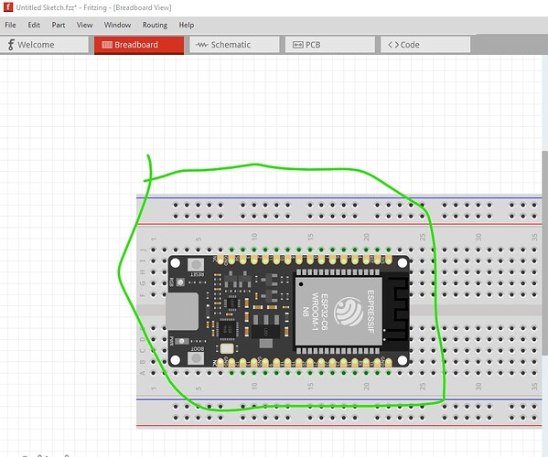
Ciao Peter, I had to change something. Now It does not fit properly anymore onto the breadboad. Can you please help me with the last step?
Thank you.
ESP32-C6 Dev Kit N8_v2.fzpz (77.0 KB)
This is the file
For me it is working fine on breadboard.
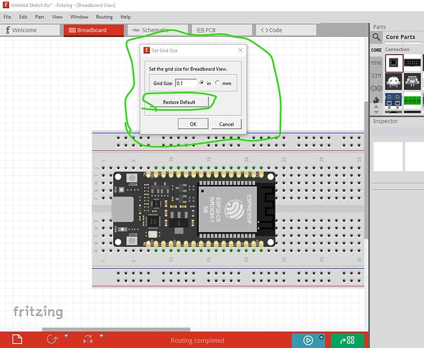
things to check is your grid size
if it is something other than 0.1in (in which case click restore default which will fix it) that will cause this. You have a couple of other problems though. FritzingCheckPart.py flags a number of errors:
Error 69: File
‘svg.breadboard.ESP32-C6 DevKit N8_cf74d2bcd15da773a4e76cbc98684189_5_breadboard.svg.bak’
At line 13
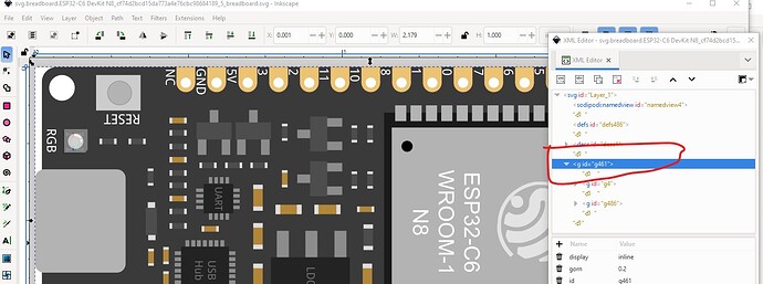
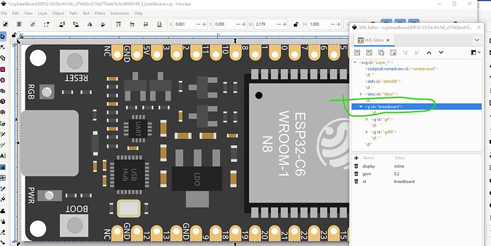
Found a drawing element before a layerId (or no layerId)
That is caused by this (and will cause the part to not export as an image!)
which is fixed like this:
Error 69: File
‘svg.schematic.ESP32-C6 DevKit N8_cf74d2bcd15da773a4e76cbc98684189_5_schematic.svg.bak’
At line 22
Found a drawing element before a layerId (or no layerId)
Error 18: File
‘part.ESP32-C6 DevKit N8_cf74d2bcd15da773a4e76cbc98684189_4.fzp.bak’
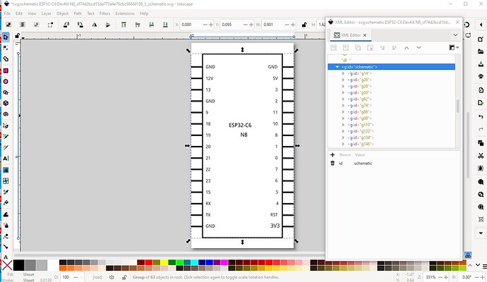
Same for schematic:
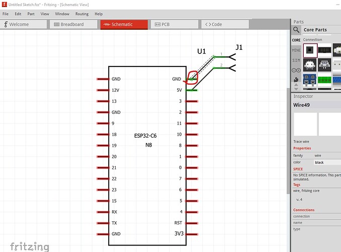
needs an Edit->select all then Object->group and name the group schematic like this:
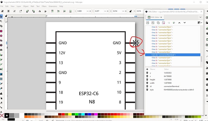
Schematic also needs terminalIds (and format changes) The easiest way to do that is to use Randy’s Inkscape extension to make a schematic. That is covered in the tutorial. Otherwise you need to do something like this:
current svg with a connector0terminalId added (which will connect the wire to the end of the pin and align the part correctly to the grid.)
which that this is caused this in schematic view:
the pins are aligned to the grid in the middle of the pin which is wrong. To correct that you need to add terminalIds like this
Connector connector2terminal is in the fzp file but not the svg file. (typo?)
svg svg.schematic.ESP32-C6 DevKit N8_cf74d2bcd15da773a4e76cbc98684189_5_schematic.svg.bak
Error 18: File
‘part.ESP32-C6 DevKit N8_cf74d2bcd15da773a4e76cbc98684189_4.fzp.bak’
Connector connector0terminal is in the fzp file but not the svg file. (typo?)
svg svg.schematic.ESP32-C6 DevKit N8_cf74d2bcd15da773a4e76cbc98684189_5_schematic.svg.bak
Error 18: File
‘part.ESP32-C6 DevKit N8_cf74d2bcd15da773a4e76cbc98684189_4.fzp.bak’
Connector connector16terminal is in the fzp file but not the svg file. (typo?)
Peter
Ciao Peter, i just noticed, I missed sending my message away.
Thanks for your support. Same issue occured also with other parts.
I reinstalled Fritzing, now it is working. Many thanks.
