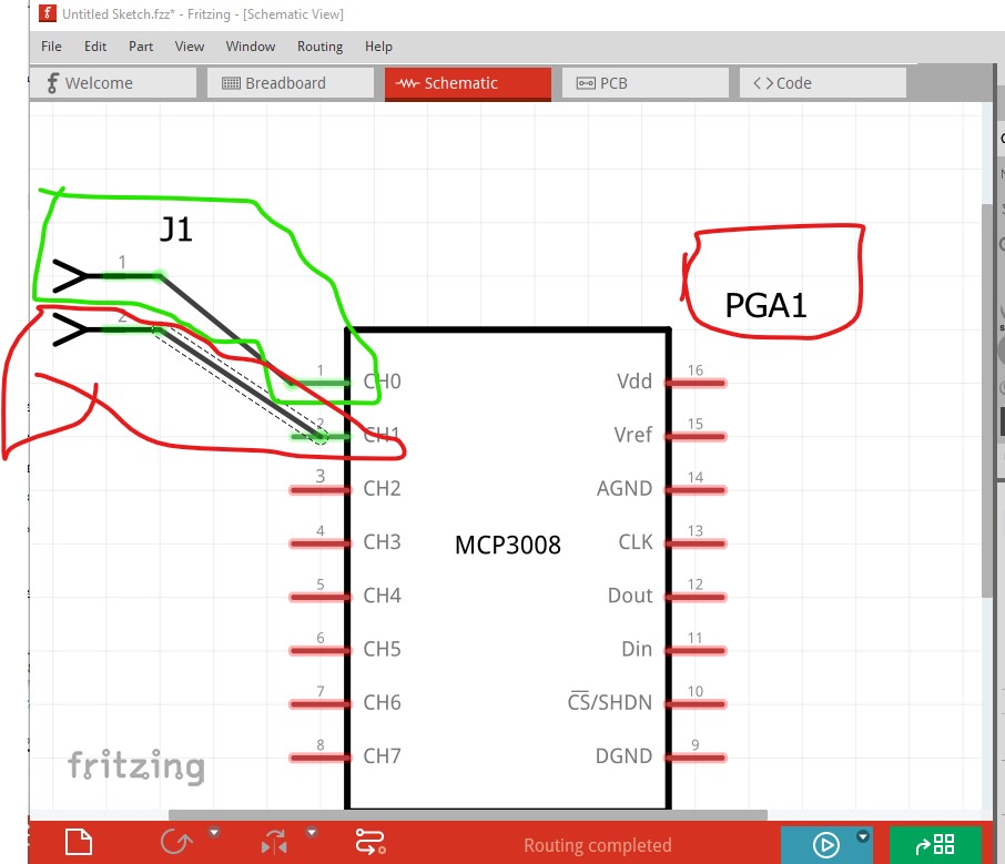
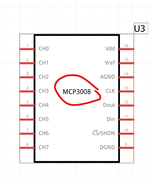
A couple of problems. You are missing terminalIds in schematic which causes the connection to occur in the center of the pin (and thus makes the part offset from the grid) and the label should be U for an IC.
I lately learned there aren’t links to the videos in Old_Grey’s tutorial so you need to do a google search for the title and then they come up on YouTube.
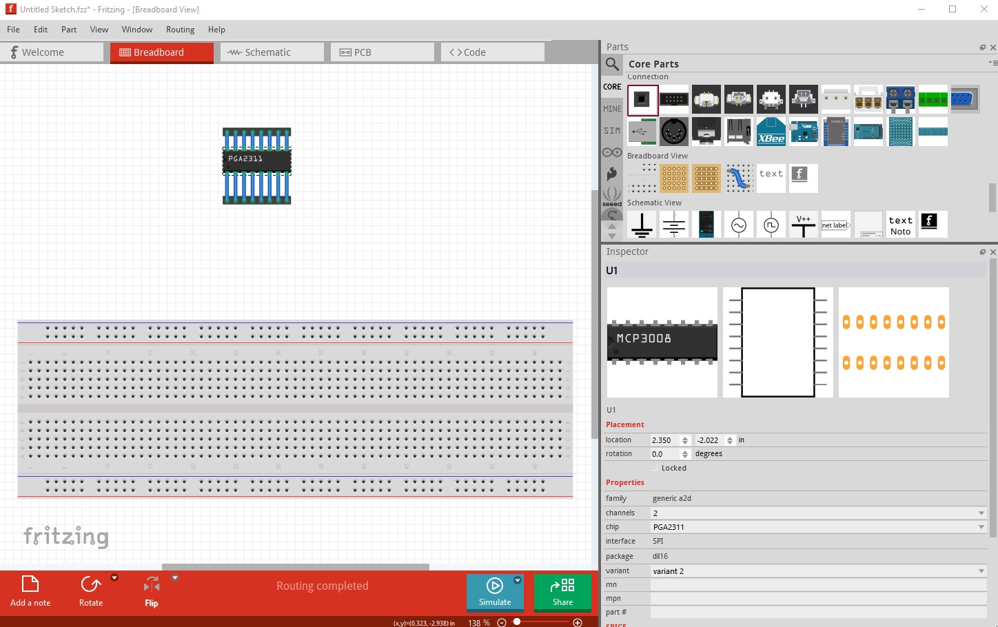
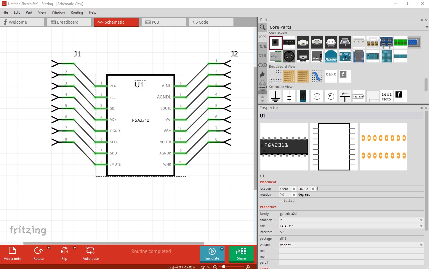
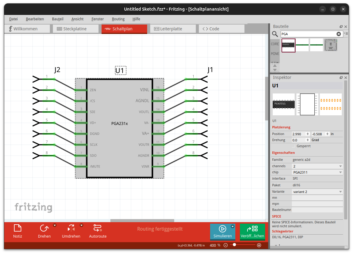
sorry for that faulty start. I have changed the part and now it is correct. I tested it on a new installed fritzing 1.0.4. All wires connecting correct and the svg now looking good…
I want to upload and change the faulty part but I can’t edit my post…
There are several ways. The easiest for someone not familiar with the .fzp file is to do what I did above and connect all the pins in breadboard then offset the header by two positions in Y (as I did in the image above) and see which ones don’t connect to the end of the pin. Running FritizngCheckPart.py, looking at the .fzp file for the part, or looking at the schematic svg and checking for correct (a rectangle not a group at the correct edge of the wire) are three other ways of doing it (but are more complex and require more experience.) The cause is a lack of a correct terminalId in the svg. As a standard practice on my parts I always test parts like this to verify all the terminalIds are correct. In theroy after Fritzing 1.0.1 Fritzing will correct this error, in practice it doesn’t always work so the test is still a good idea. Here is your corrected part done that way
Probably, but an easier solution is me editing your post (which I can do but usually don’t without your permission) to remove the original part. It appears there is a time limit on editing posts for new users (which I wasn’t aware of until @RAPTOR7762 ran in to it in a similar way) that doesn’t apply to me. Do you want me to do that for you?