That is the mark of a successful part (which this by and large is) that said a few suggestions for improvements and problems. The first issue is that the svgs are dimensioned in px rather than mm or inches. This can cause (and appears to be in this case) scaling problems. It looks like you used current Inkscape (which is 96dpi) as the breadboard svg has the pins correctly on 0.1in boundaries in the svg. Fritzing however guessed Inkscape at 90DPI so the image in fritzing is slightly too large as we see here. The 0.1 header from core parts should match the connector but the connector is slightly larger. Setting the dimensions to inches will cure this. Also the first group needs to have the id breadboard to match the layerId in the fzp file. The only effect of this is that your part won’t export as an image (svg, jpg, png, etc.) but that is annoying if you want to export it that way.
assuming the board was the correct size originally it will be slightly too large as well. Typically in breadboard we would show the front of the board (the LCD in this case) here that is a problem because of the connector, but either putting the pins in the correct place (where they will show through the LCD image or moving them towards the top a bit will work. Schematic has the same basic problems, dimensioned in px but the svg is scaled down to 90 dpi so it more or less looks right in Fritzing.
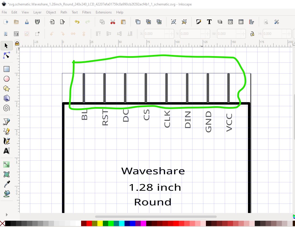
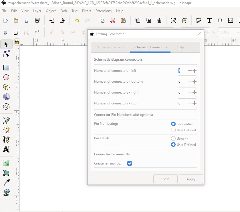
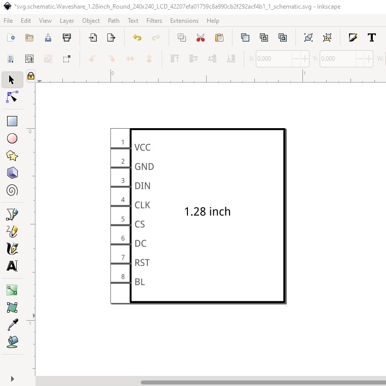
note you only get 1 line for the title so we need to add the rest later! The height needs to be 0.1in larger than the number of pins. Then define the pin layout like this. I chose to put the pins on the left (I could as easily use the top!)
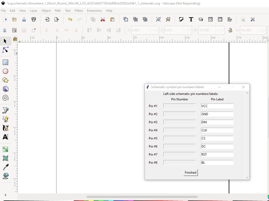
hitting finished creates the schematic svg which meets the graphics standards and has correct terminalIds (the ones in your svg are groups which won’t work and cause this
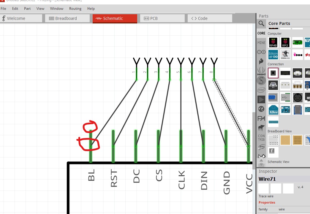
here because the terminalId wasn’t recognized the wire connects to the middle of the pin. That in turn is aligned to the 0.1in grid so the pin top is (where the wire should connect) is misaligned. That should be fixed in the new svg:
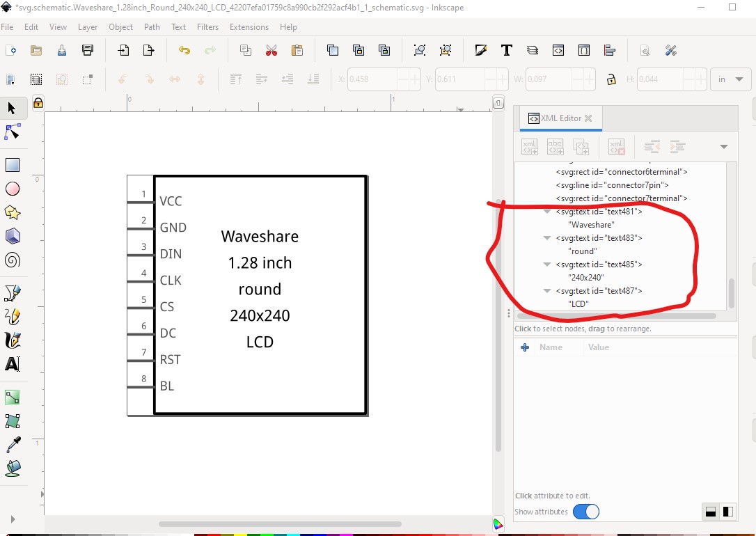
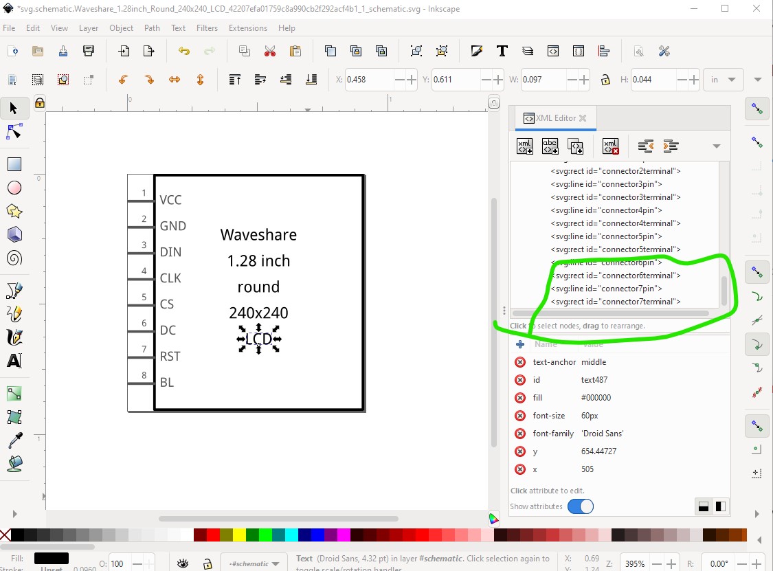
Now my additional text needs to move to the top of the svg in xml editor so the connectors are the last thing in the svg (the schematic extension does this automatically but not for manual additions!)
which leaves the svg with the proper layerId ready to be saved as plain svg and used as schematic. Which looks like this (right click and select save image as to get the actual svg downloaded!)
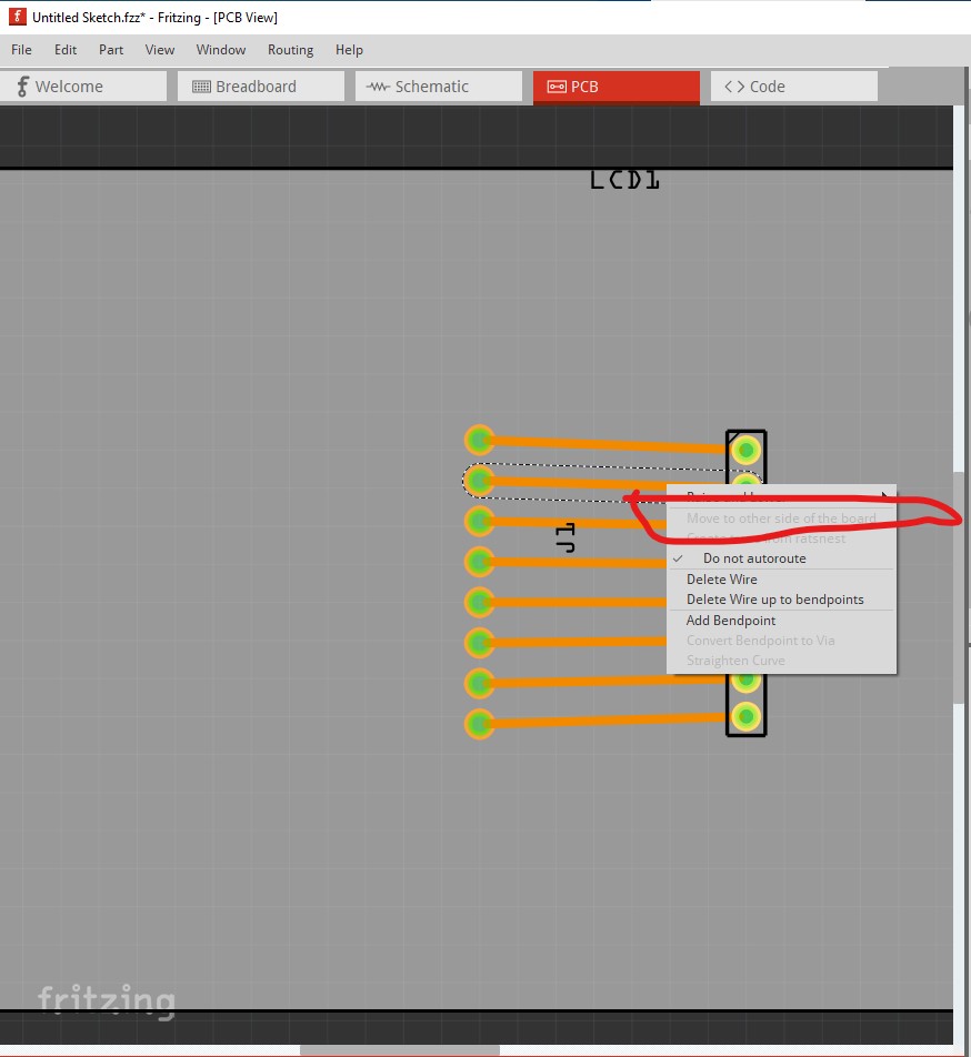
now on to pcb. Here I should be able to move the trace to the top of the board, but because the layerIds are wrong the option is greyed out.
currently pcb is a copy of breadboard and thus won’t work (the pins are also misaligned so wouldn’t fit 0.1 headers on the actual pcb.) For you that probably doesn’t matter for others it may.
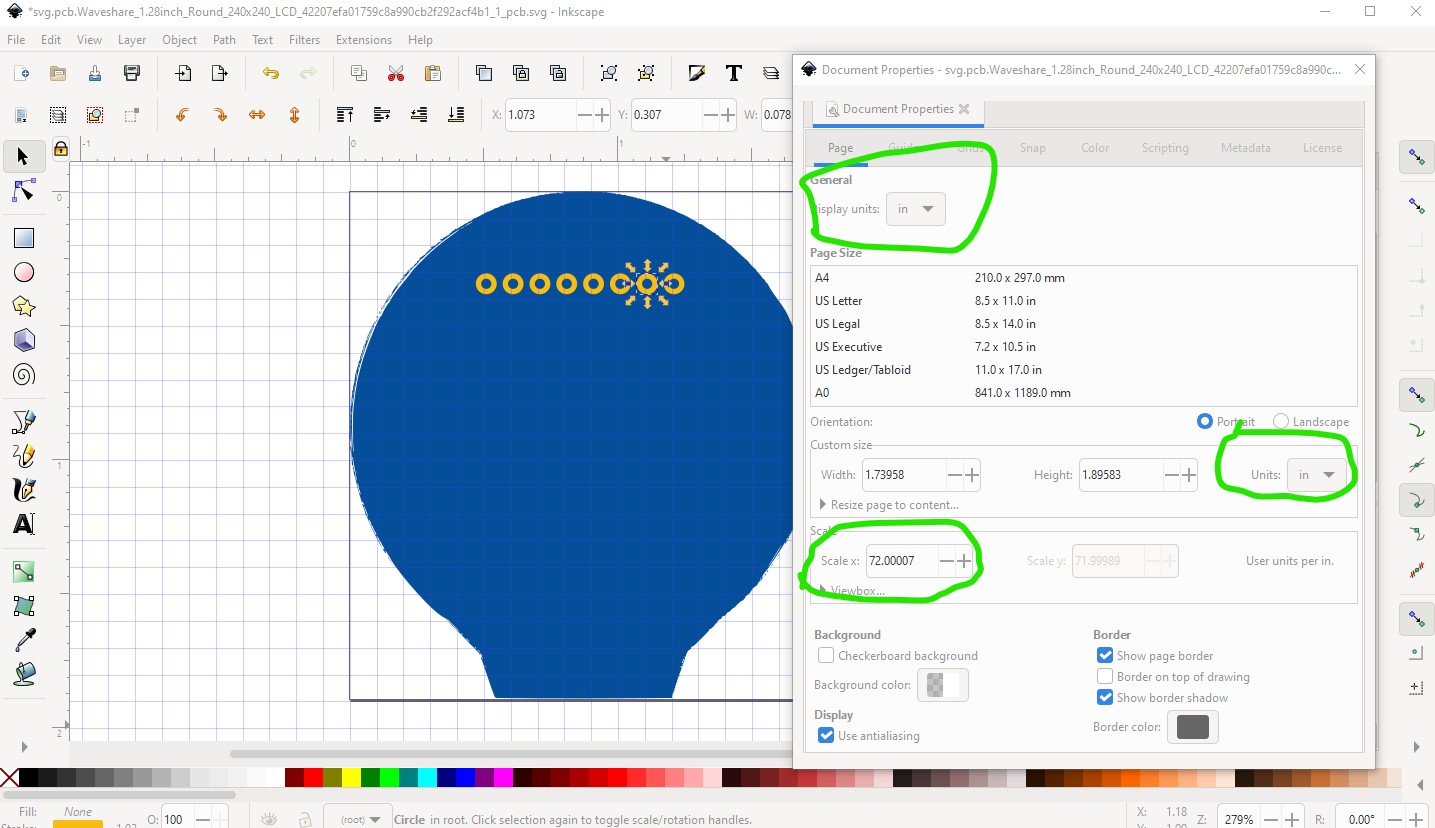
I reduced the svg to just the path (much simplified as you see) and the correct set of connectors. Then I set the svg dimensions to inches like this (in Inkscape)
I see the dpi for the svg is actually 72dpi which may mean you are using Illustrator in which case none of the Inkscape stuff will help you. There are a couple of posts in the forum of the settings for Illustrator that are working for people though. With that done I rescaled the image to the correct scale (1 drawing unit = 1/1000 of an inch) That gives us this somewhat ragged path (I would probably clean it up with a circle but didn’t here) with a stroke width of 10 to provide the silkscreen and the 8 connectors. Since the modified path crashes Inkscape then I try and resize it on to plan B which is remake the path as I said. To do that I imported the board image from here:
and imported it in to Inkscape then changed the svg like this (and will redo breadboard in a bit!)
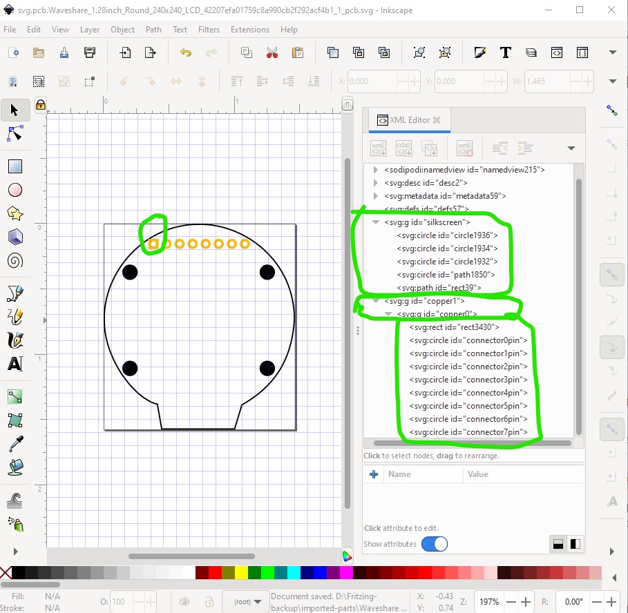
here we see the original is a little too large, and I have added holes (in silkscreen only) for the pointing screws. The pads have been moved up a bit to maybe allow wires to the connector. Removing the original path and remaking the groups (reversing the numbering on the connectors so pin 1 is on the left so the part will connect correctly when mounted face up!) should do it.
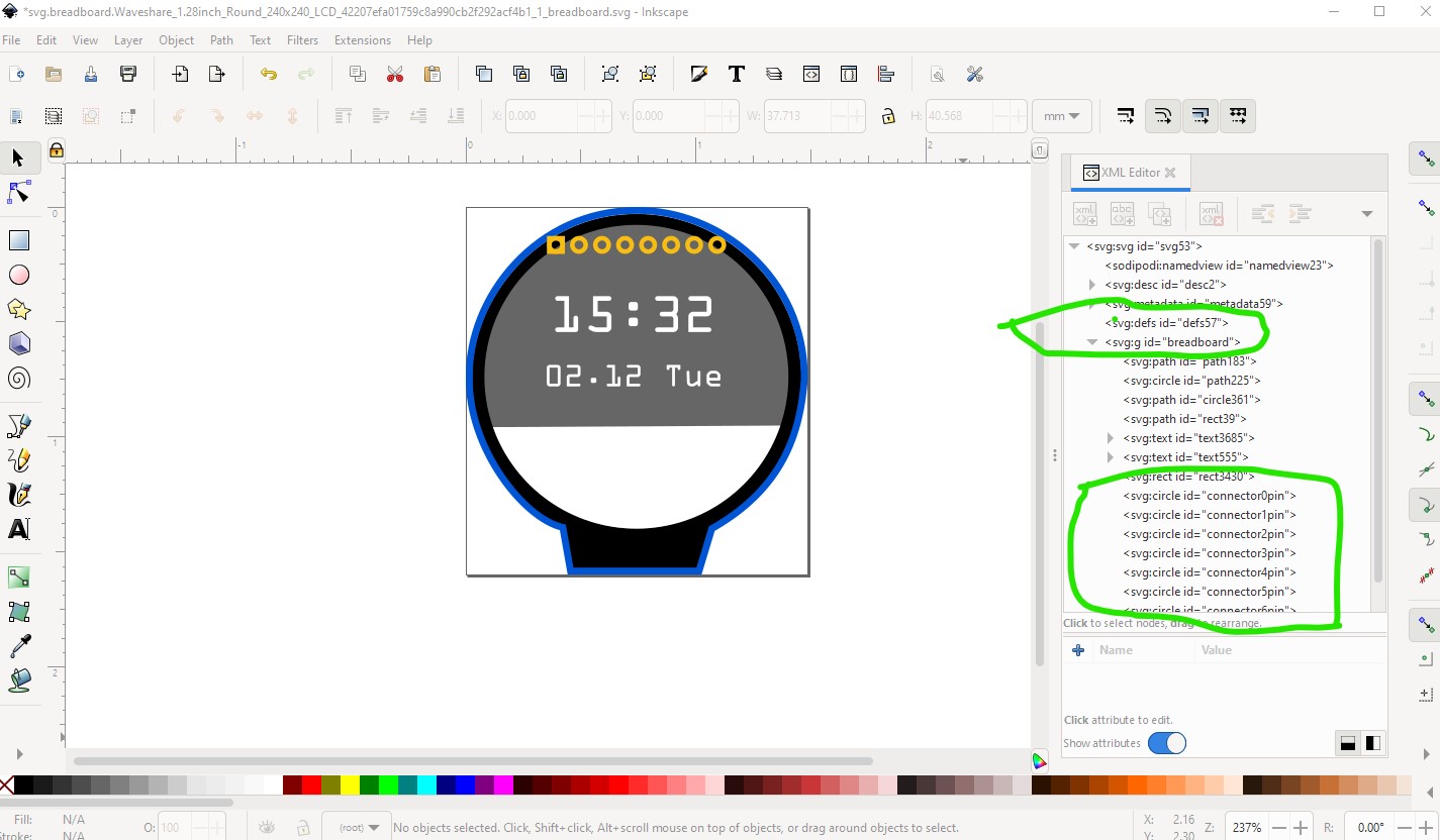
This svg is showing the LCD from the top ready to be mounted to the top of the board. With the silkscreen consisting of the path and the 4 mounting holes and the pins being in nested groups copper1 and copper0 to be on the top and bottom of the board respectively. Now use this svg to remake breadboard to also show the view from the top (the face of the LCD) like this
here the entire svg is named breadboard to give us the correct layerId and the connectors are at the bottom of the svg. All of this creates this new part (you will need to delete the old one before this one will load as I did not change the moduleId or filenames!)
Thank you for such detailed feedback …very informative and obviously quite a few lessons for me to learn.
Also, thank you for improving on this part …had a feeling there were a few things that needed to be addressed.
Am only using Inkscape as Linux is my preferred platform. The original svg was gained using an online conversion tool using an jpg from the Waveshare site …I guess the site hosting the conversion tool is using Illustrator (or something similar) behind the scenes.
I’ll install the schematic Inkscape extension for the next part I attempt …and will endeavour to pay attention to all points you’ve made (above) - thanks again!