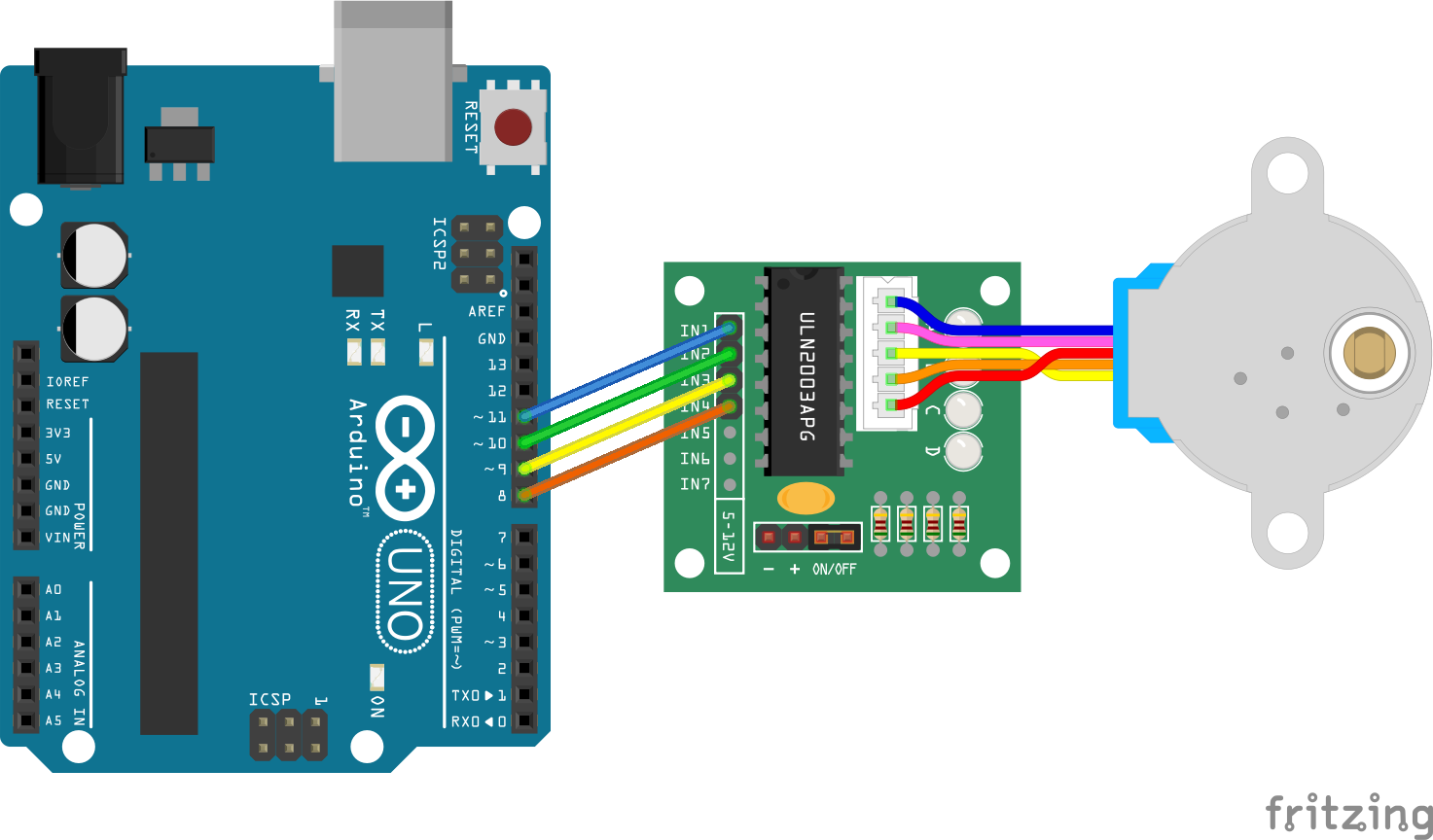
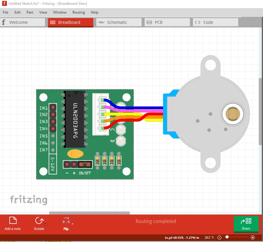
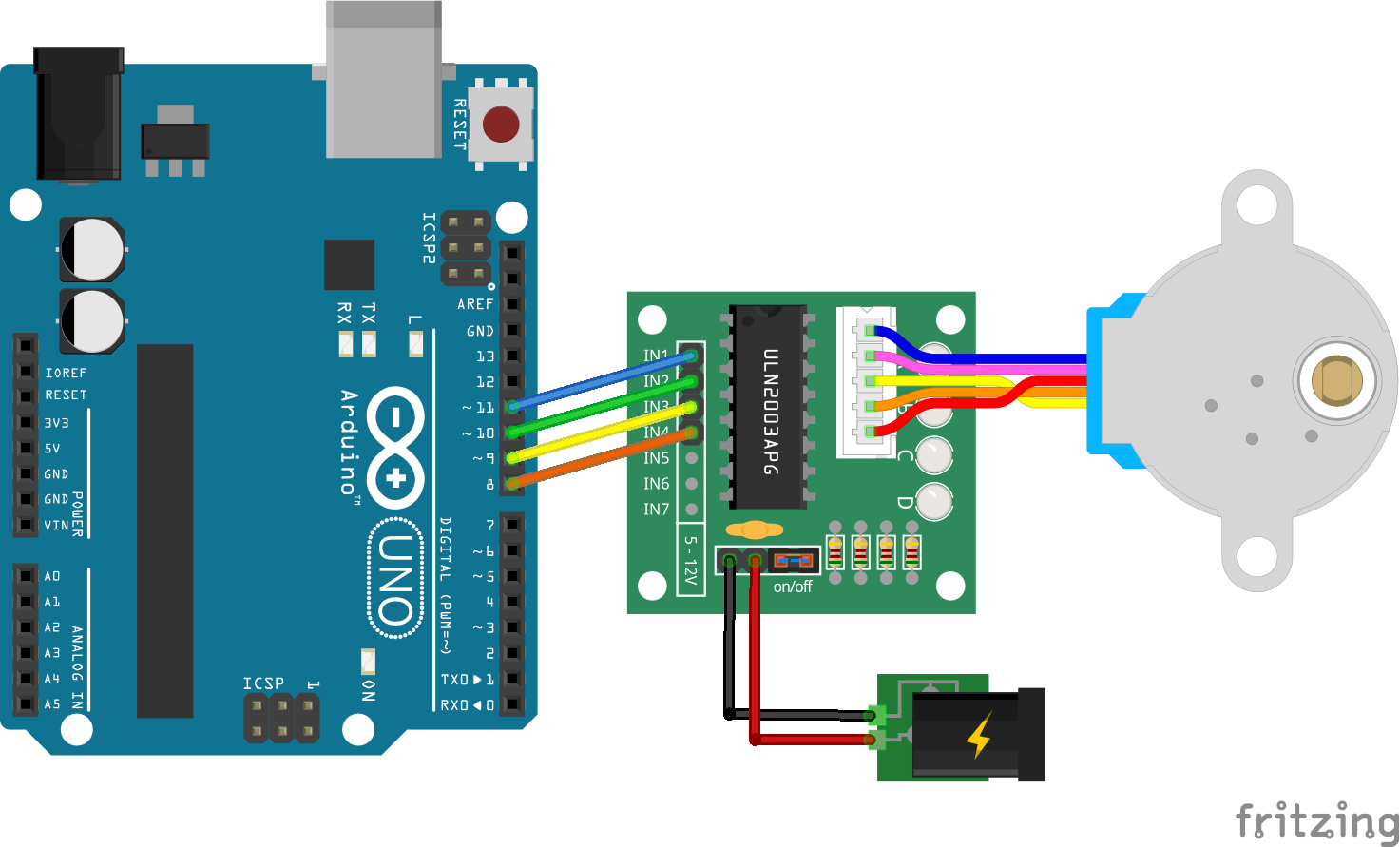
I just finished these two fritzing parts to correct many of the issues that other similar available parts have: incorrect dimensions, no JST connector, missing pins, incorrect wiring, incorrect naming, etc.
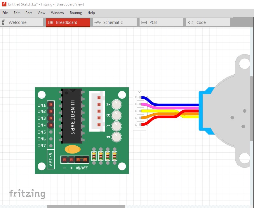
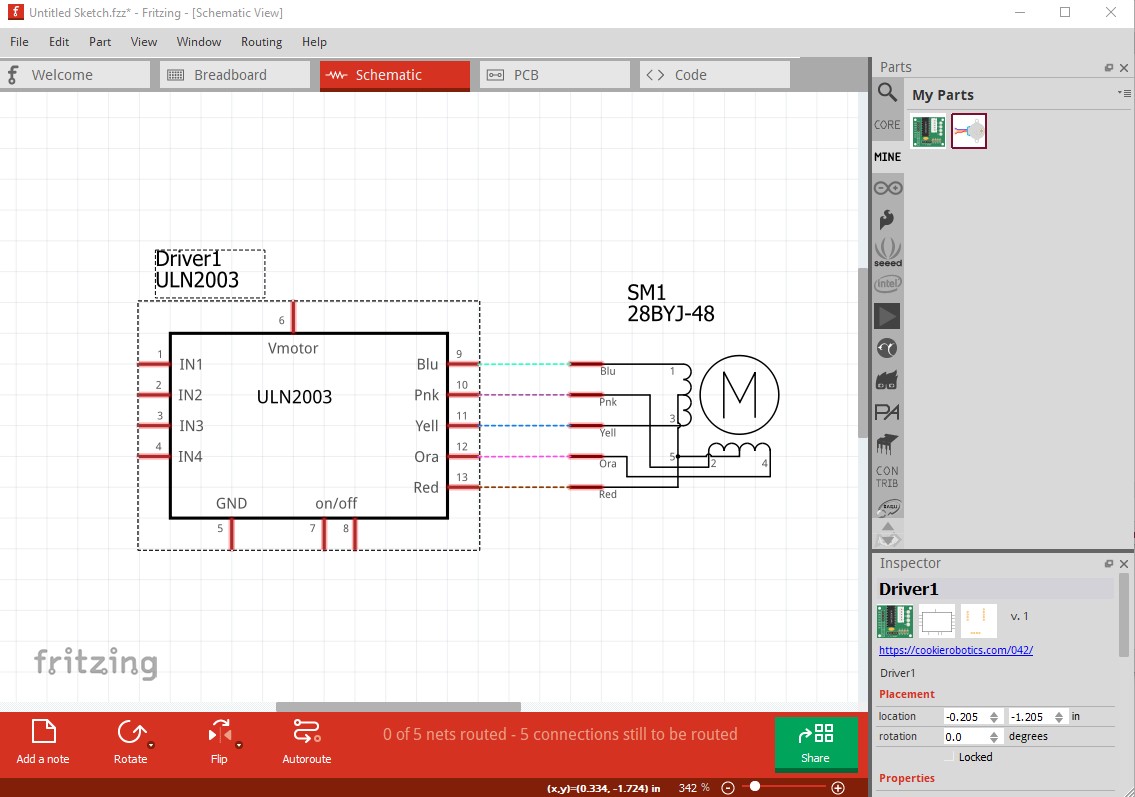
Nice job, although with a few issues. I assume because the stepper has female pins you were hoping to be able to connect the stepper to the module in breadboard and have it connect. Unfortunately the current breadboard doesn’t align on 0.1in boundaries so that doesn’t work. I moved the connectors in breadboard slightly so they all align and now that works:
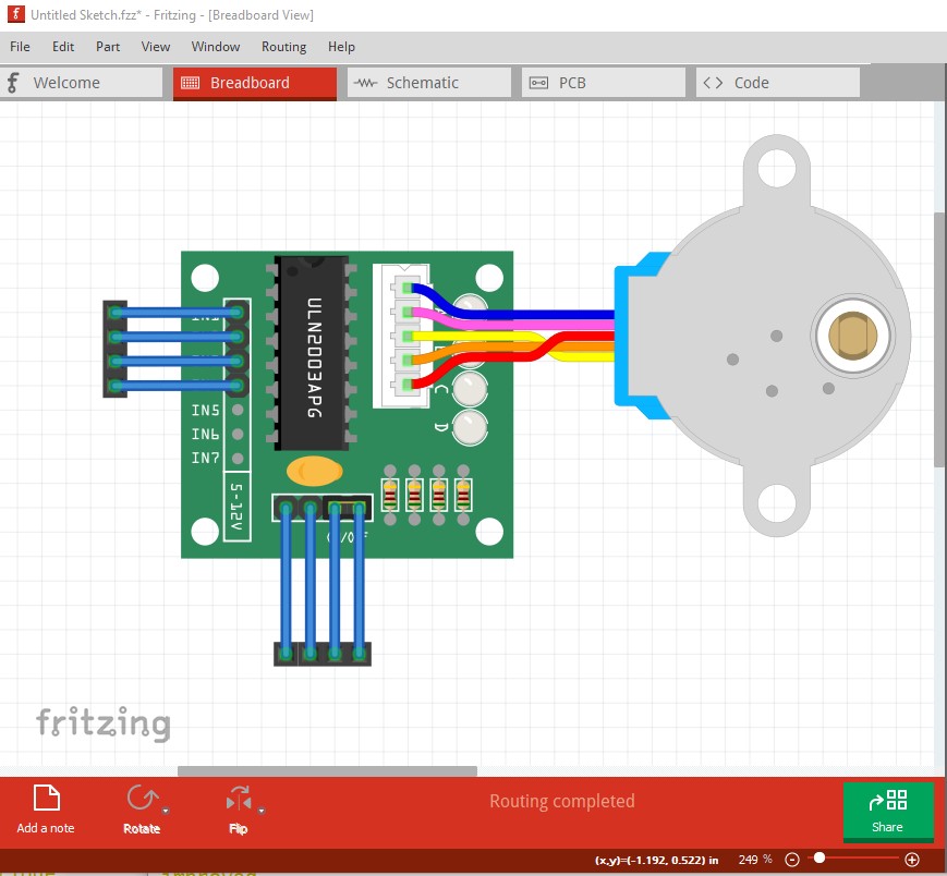
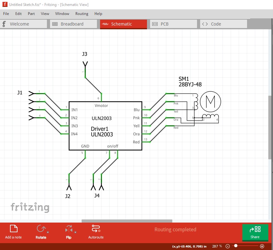
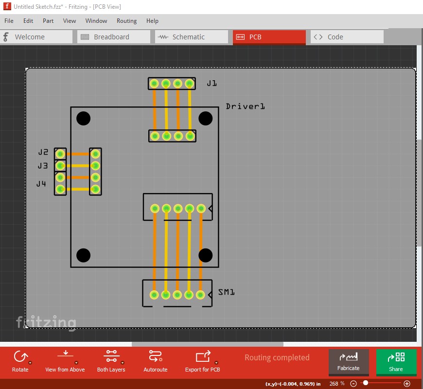
(you will also notice the motor schematic looks quite different to ccomodate this connection!) I also modified both the pcb svgs, in the module I removed the text as text can be added in the sketch (but the user has to change the part to remove text included in the part which is why text isn’t recommended in parts!) As well I moved the connectors to their real positions and added circles for the mounting holes in silkscreen (again if the user wants the mounting holes they can drag a hole part in to the sketch to produce them, if they are in the part the user has to change the part to remove them!) In the motor the holes were slightly to large so I set them to the standard 0.038in for header pins. Here is the complete test sequence of the two parts (including gerber output)
Thank you very much for your report @vanepp: I’ve updated the parts taking into account your changes/suggestions, although not all of them, as I consider some to be overcorrections:
You removed my Icon view for the motor, which was different from the Breadboard view.
The JST connector has a pitch of 2.50mm, not 2.54mm(0.1in) as per your corrections.
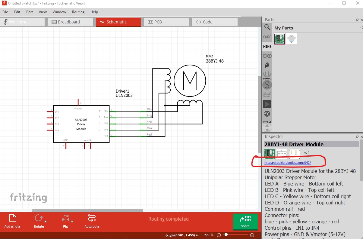
The motor schematic symbol has been updated following your idea but respecting my own original drawing and accurate info (which coil lead connect to where, naming, etc.).
In the driver schematic symbol I decided to keep the whole name to differentiate it from the ULN2003 IC: it’s a module, not a breakout board.
My original part worked fine: it was NOT a problem of alignment (did you try the attached FZZ file?) but, as you mentioned, a question of pins genre. The spacing was not perfect (now it is as I sacrificed/traded accuracy for usability), but it appears that Fritzing assumes female pins to be in the bottom (because of the breadboard?) and male pins on top when you drag some part into another (to connect), so the weird effect result is that you had to connect the driver board to the motor, and not the other way around. It was unnatural so I swapped the pins genre in the JST-connectors for both the motor and the driver and it’s easier now (again, traded accuracy for usability).
I didn’t find this. What I saw instead is that you changed the JST connector pins from 2.50mm to 2.54mm(0.1in), that was not a problem anyway.
I won’t use Fritzing to create PCB’s (I use KiCAD) so I followed your recomendations there, although it doesn’t make any sense to me to use the PCB footprints for this two parts, especially the driver itself, as it is a module with THT components that won’t fit in a PCB (but I’m no expert in these matters )
Inkscape, but nothing unusual (at least for Inkscape, and no where near as much crap as Inkscape adds if you let it save as an Inkscape file rather than plain svg!) and nothing that Fritzing objects to.
Yes, but as you note I was moving the motor not the interface board and that indeed does not work. I agree if I move the interface board then it connects correctly (and I think that is a Fritzing bug as it should be symmetrical)
I would agree, but it was there, so I corrected it. Even if it doesn’t make sense I often add pcb with at least header pins so if someone wants to include it in a pcb they can (presumably by connecting wires from the connectors.) If I’m lazy I suppress pcb view.
It was for me: my inkscape doesn’t generate those metadata fields, that’s why I doubdted
Out of curiosity, I’ve been looking around and you produce a lot of parts: would you mind sharing your process of part creation/editing? (tools, steps, environment…) I’m specifically curious about how do you test small changes, because for me it is very time consuming just the simple repetitive steps that go from “updating the svg” until you can actually check the part in Fritzing. Maybe I should start a topic just for this subject…
fair enough.
another interesting question: how do yo generate the SVG line elements (used in the connectorXXpin parts of the drawings)? Inkscape can’t produce them (although, oddly enough, can manipulate them…).
describe what I do. I have some tools (some published on github some not) that will create fzp boilerplate for connectors, (FritzingCreateFzpConnectors.py on gighub) and these 3 which need more work before they are ready for prime time
SvgRenumberConnectors.py renumbers connectors in an svg. At present I modify the python code to do what I need on the fly, that needs to be generalized so it can be controlled from the command line.
SvgSetConnectors.py
SvgSetConnectorsbb.py
These two (SvgSetConnectors.py for schematic) and SvgSetConnectorsbb.py for breadboard and pcb) take an svg with the connector pins at the bottom of the svg, with the first connector labeled connectorxpin (I think connector anything works) and assigns the pins sequentially. SvgSetConnectors.py looks for a line followed by a rectangle (pin and terminal) where SvgSetConnectorsbb.py looks for only the connector and assumes everything after it is another connector. This allows me to move the pins and terminals in order in a svg without typing the pin numbers then run the svg through one of these to create the correct pin numbers. On large parts that saves a lot of time. Again the two scripts need to be merged in to one with command line options to control behaviour (after I finish the new version of FritzingCheckPart!)
I don’t know of any shortcuts here. This is usually the most time consuming part and is covered in
in the tutorial series. Hopefully more can be done in FritzingCheckPart eventually, but I am having enough trouble just updating it to not have false positives so it can front end parts submission on github. A number of places it will sometimes complain about something that is in fact fine. For its original purpose, that is fine because the output goes to a human, but as a part of automated part submission, it is not.
edit:
Forgot this one:
Yes the line is an Illustrator construct but I like it. Both copy/paste and duplicate in Inkscape will deal with line, so I copy / paste from an svg that has one if there isn’t one and duplicate to get more once I have one. The schematic template uses them already and I often replace schematics with a copy of the template (which is the correct scale with the correct pins and terminalIds and the correct colors to match the graphic standard) instead of trying to correct an existing one in Inkscape.
@roboteach. Just want to thank you for the 288BYJ-48 and the driver. I purchased Fritzing today but couldn’t find or modify the components I need. I was about to give up when I found your motor and module. Many thanks.
Barrie
If a google search of the form “fritzing part part-number” doesn’t turn up a suitable part, you can ask in here. I will usually make parts for folks (as making parts is not particularly easy unless you are experienced at it.)
I think so but haven’t done it in a couple of years (github and I tend to not get along that well ) so I’m not sure. You want to make the pull request against the development branch these days I think (the docs may still refer to nightly build which I think has changed.)
Mostly fine, it would be preferable to run the parts through FritzingCheckPart.py to remove the px from the font-sizes or edit the svgs with a text editor and remove the px from font-size although it doesn’t appear to be causing a problem currently, if run through the parts editor to change something it probably will. Other than that the url in the driver should likely be changed to this
to reflect the actual board rather than the motor as it does currently.
I did! but then made some new changes in Inkscape, and the “px” were bak, and forgot to re-check…
I updated the parts now, also to include a new URL, but not the one you suggested (I prefer to include info/documentation/manufacturer links).
Best regards!
PD: I have also a suggestion for your tool, if the file is not changed (only warnings or when it’s OK), don’t generate the .bak file by default (it’s annoying, at least for me).
Hard to do, because the file is pretty printed (which changes it), and likely changed due to px and the inlining of style commands. I’'m (very slowly!) working on a new version that only checks (changes nothing) which would do what you want and a different version that makes changes.
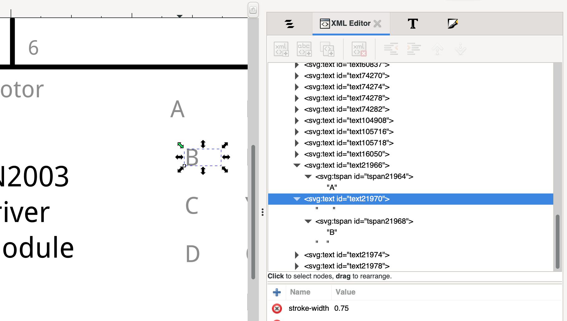
Well, now I understand what was happening to me: that “pretty printing” is breaking the svg files to the point where Inkscape interprets <text> elements as three lines, one for each return+indentation. Take for example the schematic view por my “ULN2003 driver module” and see what’s happening:
in my local copy, for the text element that contains the “A” I removed every character separating the <text> tag from the <tspan> tag and Inkscape works fine, as for the “B” (that still is as the tool leaves it), there is text (spaces) before and after the <tspan> element, because of the “pretty printing” linefeed+indentation.
And that’s because every character in a <text> element is part of the text itself, so it’s working as it should…
So, that’s a bug, isn’t it?
Nice to hear. Keep the good work!
Best regards!
EDIT: find attached a zip file with an example of the “problem” before and after passing the tool. test.zip.fzpz (1.2 KB)


 )
)