Yes another newbie ! I have never designed a PC so this is a steep learning curve. I’m trying to create a new part, all the information that comes up either said “this is out of date as we have updated it” and sends you to a link that doesn’t show how to make a part, or shows how to edit a part.
I’m trying to add a PCB mounted dual 18650 battery holder, can anyone help ?
A google search for “fritzing part dual 18650 battery holder” turns up the single version I did some time back in the forums here (as does a search of the forums) and this one on github:
With the lack of a step by step guide on how to create new part in the new part creator from scratch your help would be very much appreciated
If I knew how to do it I could create the graphics and export them, just can’t find out how to do this (very new at only been playing with this program today)
The battery holder I’m looking at creating in the link I posted, is a dual holder with 4 (2 x positive and 2 x negative) pins to mount on a PCB.
Here is the part. Download the fzpz file then in Fritzing file->open->file name which will put the part in your mine parts bin ready to be dragged in to the sketch. As always (because I don’t have one of these) if you are making pcbs you should print the footprint out at 1:1 scale and check the footprint against a real part. As well if you want the mounting holes in the pcb you will need to drag a hole from the pcb part of the core parts bin over the hole in the silkscreen layer and set the hole size correctly (the drawing doesn’t have a hole size so I used 3mm).
Thanks for your replies, sorry for my delay in getting back to you. As with most apps when you first start using them it’s a up steep learning curve, I’m slowly getting my head round it. I find knowing the right question means you will get the right answer, the problem is knowing the right questions to ask !
Old_Grey
Thanks for the links, the biggest issue I hit was all the information I could find were using Inkscape, I use Coreldraw so it took a lot of digging until I found what I was looking for. The 2 main bits of information I need were the colours to use, and the ID tags (also in Coreldraw what grouping I needed to get the correct output). Its also not helped, and this a internet common problem when links are out of date, “for further info click here” which take you to the wrong page LOL
Vanepp (Peter)
Thanks for the part, I did load it but the size wasn’t correct when laying it out in the PCB view. Based on digging, Old_Grey 's videos, and the part you made I have made my own, I think its working, graphics may not be as nice as yours but the size was the most important part (no jokes please LOL)
Here is what I came up with, I think is working, if you wouldn’t mind checking it that would be great, that way I will know if I have understood this correctly.
I have hit one problem, I’m doing a custom board design, in PCB viewer it looks OK, but when I upload it to the aisler.net one of the hole was missing. Having read what I could find on custom boards, when you make a board you must “merged shape with no stroke”, the only way I can get it to work is a group of 4 objects (the 4 hols and the board) with a white stroke
A “Via” is a hole through both layers with a copper core thus joining both layer together at that point. When you place a part (in my case a Wemos D1 Mini) are the pint connects “Via”?
Your part has a number of problems, as shown in this sketch shows. While I could detail the problems, but I suspect you would be better off just unzipping my part and modifying my parts svg files and modify that.
Most of the problem appears to be that the mechanical drawing on the web site appears to be wrong about the mounting hole positions and possibly the size. Here is a new copy of the part with the mounting holes changed and your text imported:
the pads are too small and likely the wrong size. Typically pads have a 20thou stroke-width (to provide 20 thou pad width) and the hole set to one of the standard drill sizes. The alignment is not on .1in boundaries which is messy looking (since most other parts are.) Somewhere in the forum here there is a post from Steel_Goose on how to do this (I can’t find the actual post right now):
“There is a way to set the drill hole size to 0.035” in Inkscape: First, open the dialog box
“Fill and Stroke”, and click the tab “Stroke style”, set the units to Inches and width to
0.020". Now go the the tool bar and set the units to inches and the width and height to
0.075". Shazam!.. The outside diameter of the circle including the stroke-width minus the
stroke-width x 2… leaves you the inside of the circle (drill size). CorelDraw is a little
different, the toolbar dimensions are the actual dimensions of the circle and the
stroke-width is in a separate window…"
Hopefully the comment on how corel draw does it makes sense to you since you look to be using Corel Draw. I changed the size of the mounting holes to be 0.086in as that is the closest standard drill size to the diameter of your pads.
Try the new part out and see if it works better.
Yes, through hole parts connections are the same as a via assuming the board is made by a company that makes the boards does plated through holes (home etched boards are usually not plated through).
Once again thanks for your help. Yes the new part is better, I had played about a bit myself.
Based on what you have said it seem there are “standard” drill hole sizes, I can’t seem to find a list of them, is there one?
With the battery holder I know is a square pin and its about 1.5mm by 1mm, so base on what I have read online this means I need a hole of at least 1.8mm.
This means having a larger pad to solder to as this part is mounted directly onto the PCB (I’m not using the fixing holes to hold it), I’m guessing that if the hole is 1.8mm then the pad has to be at least 2.5mm, plus I have set the tracks from the battery to 100 (although I don’t know what the 100 is, I just need a nice thick track)
Now, I think this the same for Corel and is it for Inkscape, if I draw a circle at 2mm, with a stroke of 1mm, the outside diameter is 2.1mm, and the inside diameter of the circle is only 1.9mm, this is because when drawing a circle you get half the stroke on each side (.05mm) so both side would be 0.1mm, meaning 2mm - 0.1mm = 1.9mm.
So …… if I need a 1.8mm hole and a 2.5mm pad I create a circle of
They are usually obtained from your board house (common sizes are free, odd values are available but usually with an extra tooling charge for mounting the non standard drills. I use this one from AP Circuits
the ones with text are what the Fritzing parts factory amd/or core parts use for the listed part. As far as I know they aren’t documented anywhere except the source code. Your best bet for drill sizes is to check with who is going to make your boards, or if you are doing it yourself what drill sizes you have. Your calculation looks right but the best way to check is to export the gerber files then edit the drill.txt file which will tell you what drill sizes are being called for, you can check the pad size in a gerber viewer such as gerbv (it has a measurement function).
Yes, in general a google search for “fritzing part 18650 battery holder” will find parts, in this case (since I made it) I know it is in the forums and the forum search bar finds it:
Just my 2c for others looking to get 18650 holders: Get the battery first and measure it’s length, since some manufacturers will add protection chip on top of 18650 battery, which makes it 2-3mm longer, which is just a bit to much so you can’t fit it into standard 18650 holder.
Hi, vanepp, you’re really help me a lot by your github Fritzing files. Especially for the parallel 18650 Battery Fritzing parts.
I’m currious, is it possible to get just a single cell 18650 battery? I already get 7.4 Volt 18650 Battery visualization from your github. Now I only need 3.7 Volt 18650 Battery visualization.
Thanks in advance.
Soon, I’ll learn how to create Fritzing parts when I have enough internet quota to watch tutorials that created by Old_Grey.
Oh, I already downloaded and open that file before asking my previously request,
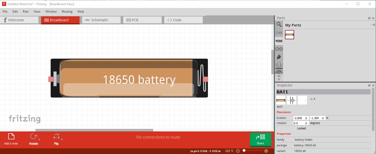
actually what I’m looking is battery cells visualization as similar as you use in the battery_holder_dual_18650 you provide in Post 4 above. brown and black color battery, with same “18650 battery” text.
I’d prefer using similarity in every sketch because I’m teaching 7 years old kids, so with same visualization, it will keep them away from confusion,
no problem if you not have time to provide it, I really need learn how to create these fritzing parts by myself later,
Anyway, thanks again for your reply, I’m appreciate your time and effort,
Ah, that makes sense. A lot easier for me to do than you I expect (part making is fairly complex!) Here is a part that has the breadboard image from the dual part.
A note of caution (which you already may be aware of!), LIPO batteries can either catch fire or explode if shorted. So if your students are using actual batteries, you may want to make sure you have cells with overload protectors in them. The usual 18650 cells do not have overload protectors although apparently some cells do now!