18650 Battery Holder Part Design

Eh, I’m really sorry, this must be really bother you, I should attach image first about what I need, :sweat:

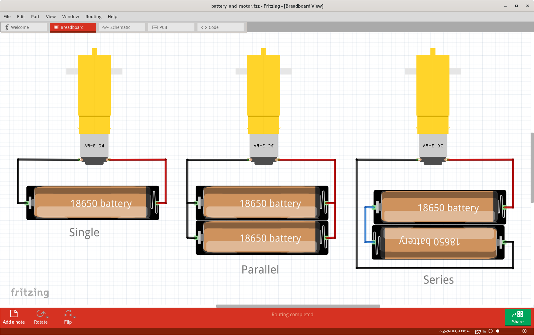
below is a wiring diagram for my lesson about Basic DC Motor, in this second lesson, i’ll explain and show effects to motor speed and torque if we use two 18650 Battery in parallel, of course the motor speed and torque will sums up,

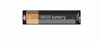
and for the first lesson about Basic DC Motor, I want to explain to them what happens if we use one 18650 Battery only, but I’m out of parts for single cell 18650 Battery for create Wiring Diagram,

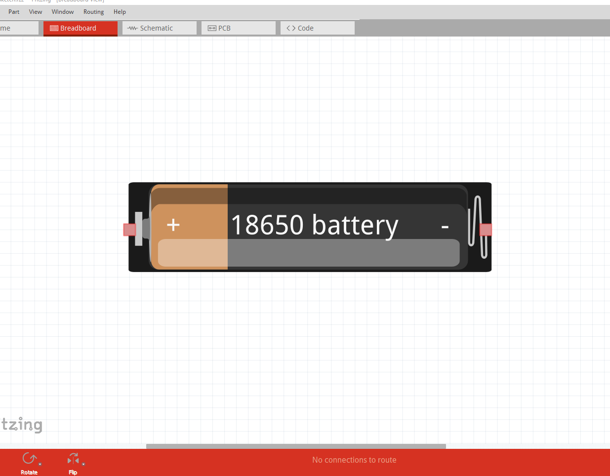
I’m planning using same battery color as part 2 in this Wiring Diagram below (which is the Battery Fritzing parts files is from you too), the Wiring Diagram will looks like this,

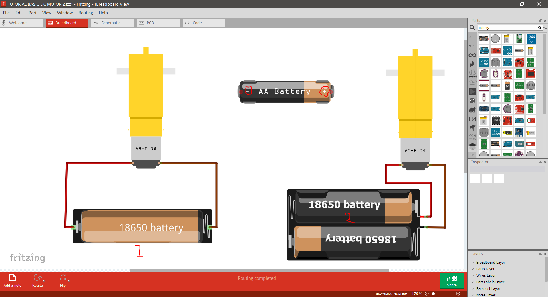
I can use your latest 18650-battery-holder-alt files that you provide previously, but it will make the kids little confused and questioning “why they’re in different colors??”

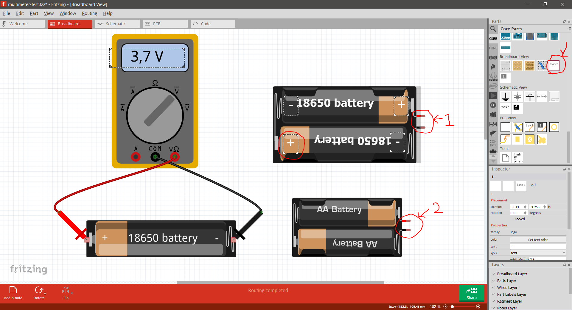
and maybe you want to add some plus minus symbols in the battery parts like the AA Battery,

so they can recognize and easily remember about battery polarity information,

I’m sorry for being choosy person :smiling_face_with_tear: I have to do this because based on my experience, kids should not be stressed out while learning about electronics and robotics, even when learning about Wiring Diagram in very early age, :smiling_face_with_tear:

ah, thanks so much again for your cautions note, I’ll explain about it to them first for keep the 18650 Battery not touching its each other polarity, (maybe with some little sparks show, so they’ll afraid and became very carefull then :sweat_smile:)

Ajie

If you can upload the Fritzing part for the dual battery holder (as I don’t have a copy of that one!) I will modify the alt part to match it.

Peter

Here is a single battery holder created from the dual part found earlier in this thread. It matches your “1” in the image. You can use this for visualization of any number of batteries by adding the right number of copies. Here is a sketch with a single battery, 2 in parallel, and 2 in series, with the breadboard view setup to “look” like it is using dual battery holders. My version of the battery part is available here, as well as the sketch the image was taken from. The battery holder will also be in the “tmp” bin for the sketch.

1x_18650_battery_holder_1.fzpz (4.2 KB)
battery_and_motor.fzz (9.8 KB)

Hi everyone,

Just so happens I need an 18650 battery holder.

I tweaked the breadboard view image of vanepp’s battery-holder-alt file posted above.

Here’s the file:
18650 battery holder_mod.fzpz (7.7 KB)

If you want any other parts posted in this thread adjusted to look like this one, just let me know…

Randy

Hi, vanepp,

Here you are, sorry if I’m bother you,

Battery.fzpz (10.6 KB)

Thanks in advance,

Ajie

Hi, Randy,

Thanks so much, this is what I looking for, its have plus and minus symbols now, kids will easily recognize it which is positive and negative polarity then,

If this not bother you, may I request it in 2 cells, 3 cells, and 4 cells 18650 battery in series visualitzation files too?? just in case in near future, we will use bigger power for bigger projects,

I’ll put this files here, I’m hoping it will have similar output like this one (little red and black cables), but this one is lack with plus minus symbols in battery’s body for mark its polarity,

Battery.fzpz (10.6 KB)

I use Battery.fzpz files above because I’m use this part below in real life:

the Battery Holder has similar output visualization too in Battery.fzpz files,

for me, its important to have similar or almost same visualization in Wiring Diagram to real life components I use for teaching 7 y.o kids, I hope you understand why I’m being choosy person here,

Thanks in advance,

Ajie,

Hi, microMerlin, actually, I’m already figure it out, connecting the batteries in series and parallel by myself using cables parts, since the single 18650 Battery files you used was already posted by vanepp before,

But I’m prefer use Battery.fzpz files I posted in Post #26, because I’m using similar parts in real life as same as the Battery.fzpz files visual, :sweat_smile:

for me, its important the Wiring Diagram visualization that I use for teaching 7 y.o kids has similarity visual with real life parts I use when teaching, so the kids will not be stressed out quickly, :sweat_smile:

But, I really appreciate your effort to replying my request, I’m sorry if I’m waste your time and energy, :pray:

It would be useful to have the web page or spec sheet for the battery holders you want to use to see what the physical layout looks like. As well the part posted has bendable legs (which are a pain to deal with) would just wires do instead?

Peter

Hope this web page link helps, the battery holders (size and physical) I use (1 cells, 2 cells, 3 cells, and 4 cells) will mainly looks like this one in this web page link,

I’m not quite sure what are “bendable legs” terms refer to the part, but its no problem if the output wires is just wires like I marked in 1 and 2,

I’m curious, the output wires that I marked in 1 and 2, is it not as easy as looks like to deal with? because I still didnt start yet to learn how to make my fritzing parts by myself yet, waiting for wifi, :sweat_smile: I didnt want to bother you further,

Also, I already figure out how to add plus minus symbols to breadboard view using Breadboard Text in Core parts, :sweat_smile:

Ajie

The ‘trick’ to get bendable leads to work in Fritzing parts, is that the connection point element in the breadboard svg must be outside of the defined boundary for the svg content. The current Parts Editor does not understand how to work with that, so had to be done with editor that allows setting the ‘extents’ separate from the actual coordinates of the graphic elements. For something like this, it is reasonably simple. Just build and save the svg file using the normal ‘full size’ content boundary, then edit the svg file with a text editor to shrink the boundary on the right, by about 0.1 inch. That will make the connection point movable, stretchable, bendable, and if line colours have been chosen correctly, they become ‘bendable’ wires.

For this type of part, it is not really needed. You can just connect a wire to the ‘fixed’ connection point, then use that attached wire the same as the bendable leg. It is more useful for discrete components, where the legs are visually not the same as wires.

It is easy enough to make parts that look like this

capture

but in practice typical 18650 batteries that I have seen don’t look like this, but rather more like this (the ones I have are in fact pink like the original single battery Fritzing part!)

which is from this Amazon web page:

https://www.amazon.ca/s?k=18650+battery.&gclid=EAIaIQobChMIzd-jhpqR9gIV4D6tBh0tegCmEAAYASAAEgJ2APD_BwE&hvadid=506542448632&hvdev=c&hvlocphy=9001528&hvnetw=g&hvqmt=e&hvrand=4467233844957237470&hvtargid=kwd-311831797667&hydadcr=19693_10111025&tag=googcana-20&ref=pd_sl_2s1ych7v79_e

The first image is more typical of the Duracell AA batteries. I would think you want the Fritzing part for the battery to look like the real life battery you are using to make things clearer, but I can make the parts either way. I would also recommend buying protected 18650 cells as this web page recommends in the protected vs Unprotected section for safety reasons. It is all too easy to short a battery by accident and have a disaster!

as the typical unprotected cell like the ones above are dangerous if shorted. You may want to source the cells first and then get the Fritzing part made to match the cells you are actually using for maximum clarity.

Peter

Not really needed as these things can vary a lot. It’s not like you need to design a PCB footprint for the thing. The single cell holder, maybe you would want a PCB footprint for. Multiple cell battery holders wouldn’t be mounted on a PCB normally. Or at least, that’s my thoughts…

Anyway…

1x, 2x, 3x, an 4x, batteries.

1x_18650.fzpz (7.8 KB)
2x_18650.fzpz (11.2 KB)
3x_18650_Battery.fzpz (12.8 KB)
4x_18650_battery.fzpz (13.5 KB)

But I also agree with Peter…

Most 18650 batteries I’ve shopped for are either light blue, dark blue, or light green in color, not the black/copper colors posted so far.

I can change the batteries color as needed, but the copper/black color is not a color combo available for these batteries.

Randy

1 Like

Proably true for the OP use case, but,

Aren’t some of the battery packs designed to be mounted directly on a pcb? With connectors and mounting holes?

Yes, the original two both are with appropriate pcb layouts. These ones not so much, they connect via wiresand have a screw hole in the bottom of the case (2 screw holes for the multiple battery ones.)

Peter

1 Like

Oh, I get it (40 percently get it, :sweat_smile:), I’ll learn it further later,

Thanks for your explanation, I really apreciate it,

Ajie

Ah, yeah, glad you notice it out about Duracell AA Batteries colour looks alike, because I’m still quite strict about similarities parts in Wiring Diagram vs real use,

but for this one, I made little exception, at least it has information, especially about plus minus symbols,

To be honest, I’m using this brand battery in my project,

I know Ultrafire brand has bad stigma among hobbyst, even “fire” words in its brand name can make me quite frightened enough, :sweat_smile:

Maybe in future, I’ll attach circuit protection in its Battery Holder body, something like overdischarge protection, reversed polarity protection,

Ajie,

Aha, big thanks, just_randy, I’m really appreciate it,

I’m quite envy now, I really need to learn how to design Fritzing parts by myself, who knows I can help someone in future then like you,

for everyone in this thread, thanks so much, guys, you rock!!

Ajie,

These may be a better bet:

A brand name battery with internal protection. Note the protected cells are about 2mm longer than non protected. It looks like your battery holders should take either, but it would be wise to buy a single protected cell and check that it will fit the battery holder.

Peter

1 Like