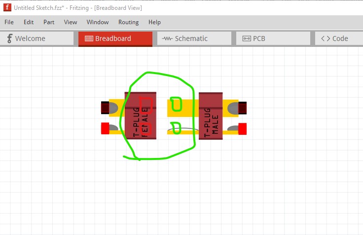
Why would you want them in one file? Typically one sex will be on a board and the other sex on another board or external power supply I’d expect. With some work (and some fairly annoying limitations on movement) it is possible to cause a connection in breadboard as you show (male connected to female) to reflect as a connection in to schematic. The annoying limitation with doing that is that you need to move one part (which has male pins) on to the other part (with female pins) in order for it to connect. The other way (moving female on to male) will not connect.
To do that you need two more connectors on each (green squares and red squares in this image) and to group the current connectors and the associated new connector. Then set the red squares to be of type female in the fzp file and if you move one over the other in breadboard they will connect and reflect that connection in schematic and pcb.
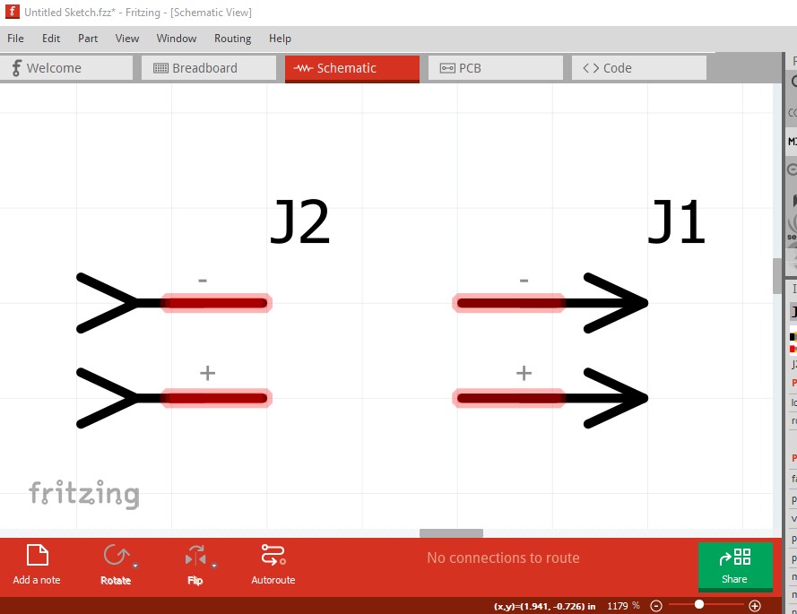
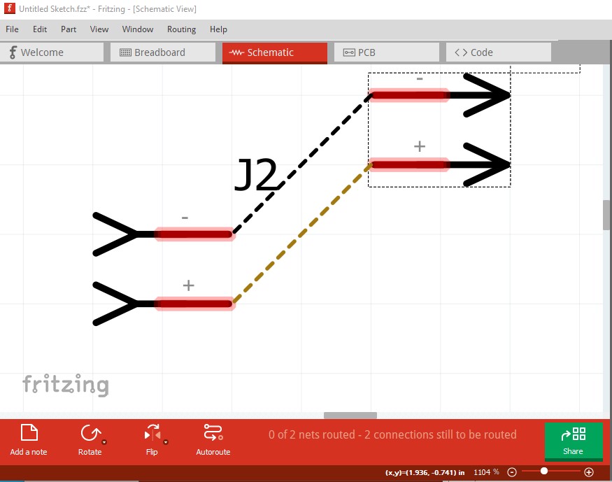
Schematic is missing terminalIds and thus the part is misaligned
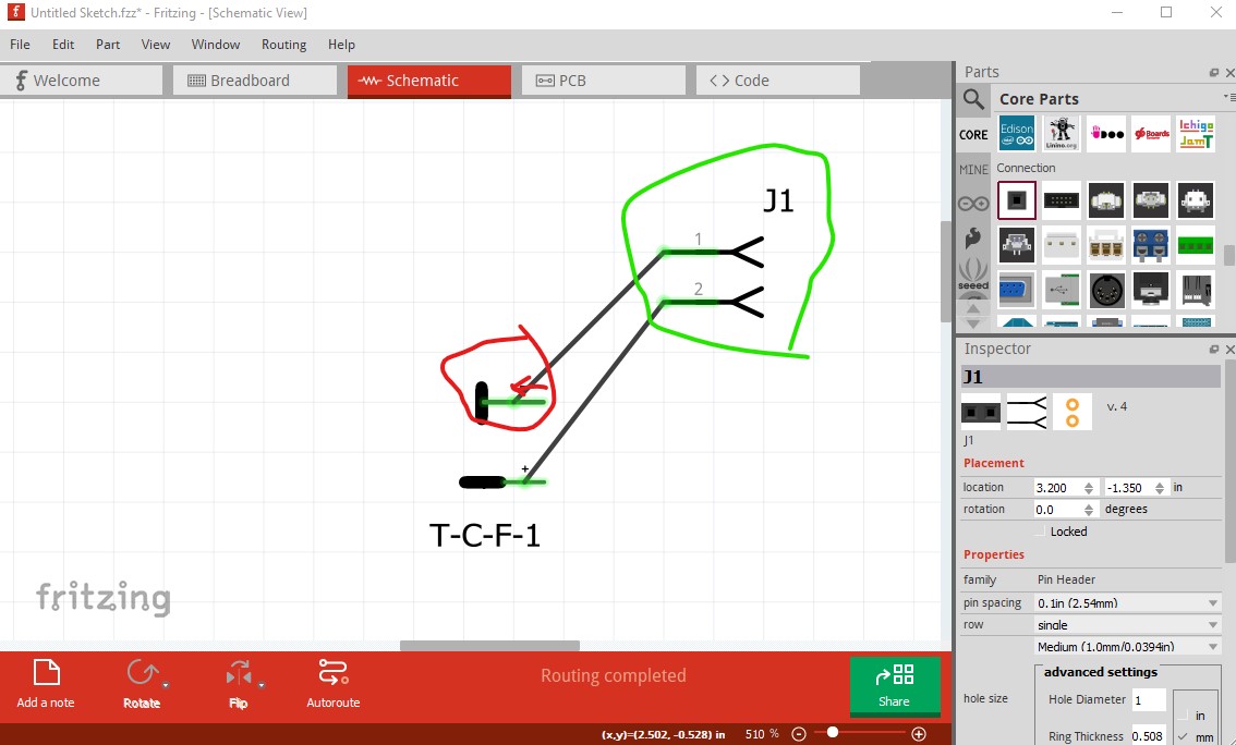
note the wire connects to the middle of the pin rather than the end as it should. In turn that means that the end of the connector is not on the 0.1in grid as it should be but rather is in the center of the pin. As well the schematic symbol should probably look like the male and female headers rather than the physical part. In PCB it would be more practical to have a circle (as with the headers) which a wire will connect in to. As well the part doesn’t pass DRC (routing->design rules check) as it thinks there is an overlap although the gerber output indicates there shouldn’t be one. That may be translates in the pcb svg.
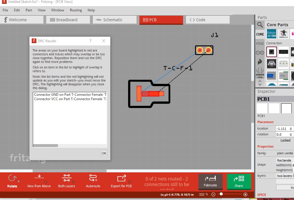
As noted this layout isn’t practical because the actual connection would be a wire from the actual connector to the board which needs a circular pad like the header. If you haven’t seen them, these tutorials on parts making may help
edit Starting from these two new parts
T-Connector Female.fzpz (27.5 KB)
T-Connector Male.fzpz (28.4 KB)
(I didn’t change moduleIds so you will need to delete your current parts and restart Fritzing to load these two)
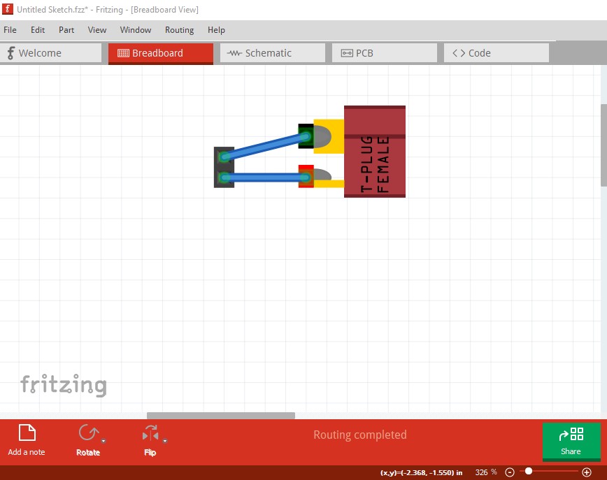
You can connect the parts together and they will connect in schematic and pcb like this:


here move the female connector right to connect to the male connector (the other way won’t work!) and it will connect in schematic and pcb like this
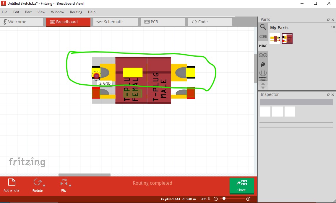
clicking on the left pin indicates it is connected to the right pin on the other connector and in schematic
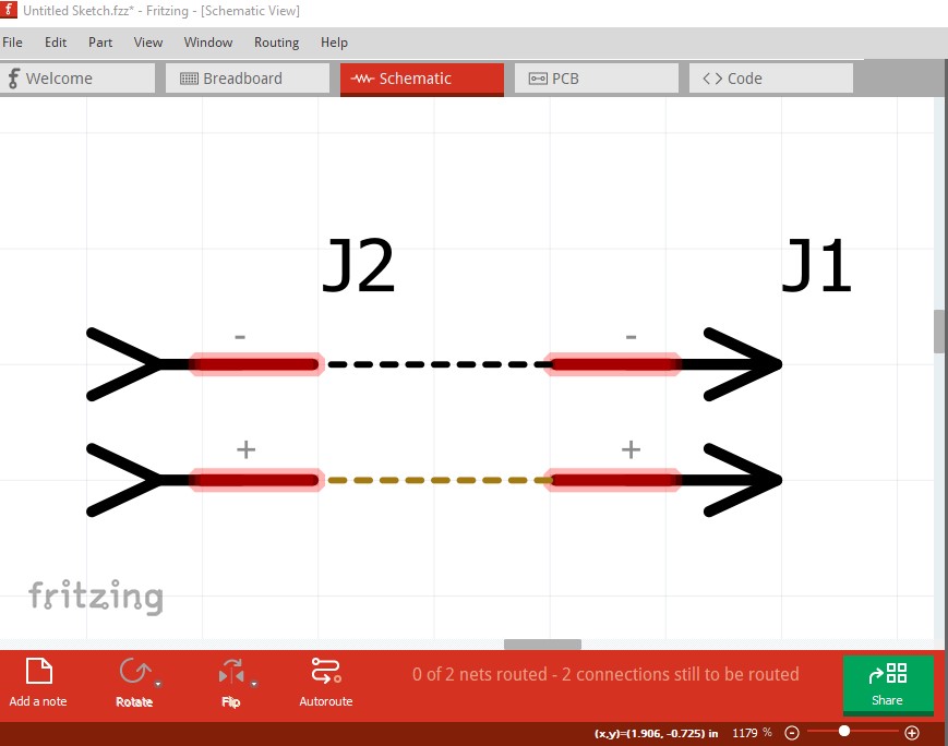
and pcb
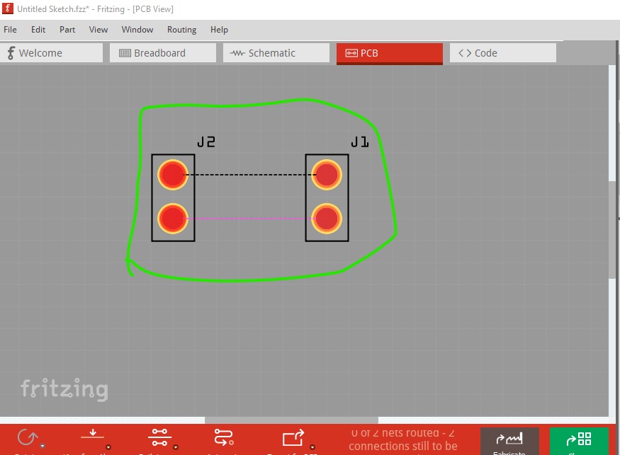
note pcb has changed to pads with a hole size suitable for 12ga wire (I don’t necessarily expect anyone to use this, but if they want to it is there!) If you unzip the two .fzpz files you can see the changes I made to do this. As well schematic has the correct terminalIds and thus aligns to the grid and connects correctly to the wires.
Peter