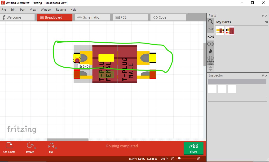
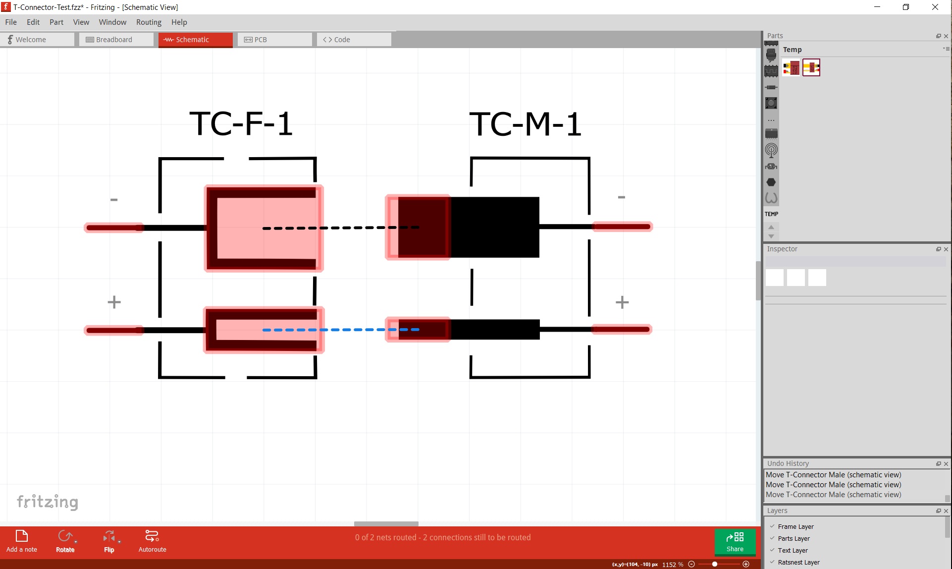
Why would you want them in one file? Typically one sex will be on a board and the other sex on another board or external power supply I’d expect. With some work (and some fairly annoying limitations on movement) it is possible to cause a connection in breadboard as you show (male connected to female) to reflect as a connection in to schematic. The annoying limitation with doing that is that you need to move one part (which has male pins) on to the other part (with female pins) in order for it to connect. The other way (moving female on to male) will not connect.
To do that you need two more connectors on each (green squares and red squares in this image) and to group the current connectors and the associated new connector. Then set the red squares to be of type female in the fzp file and if you move one over the other in breadboard they will connect and reflect that connection in schematic and pcb.
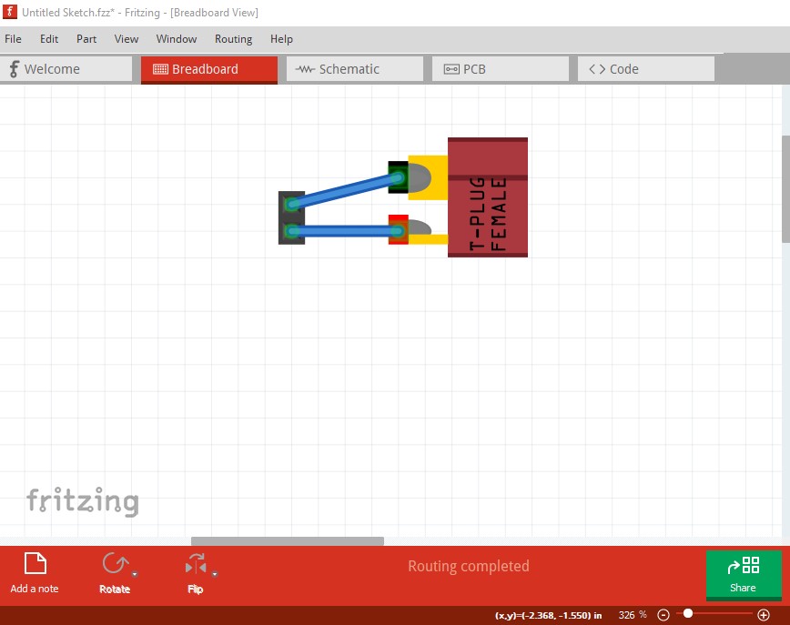
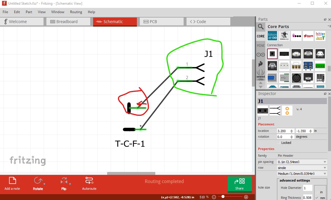
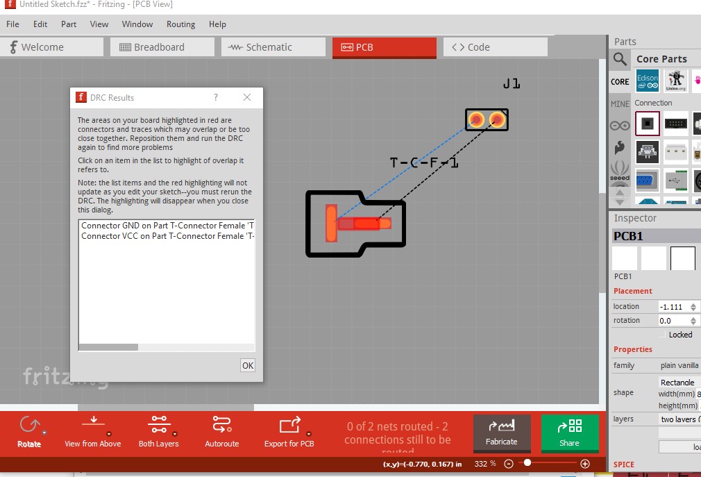
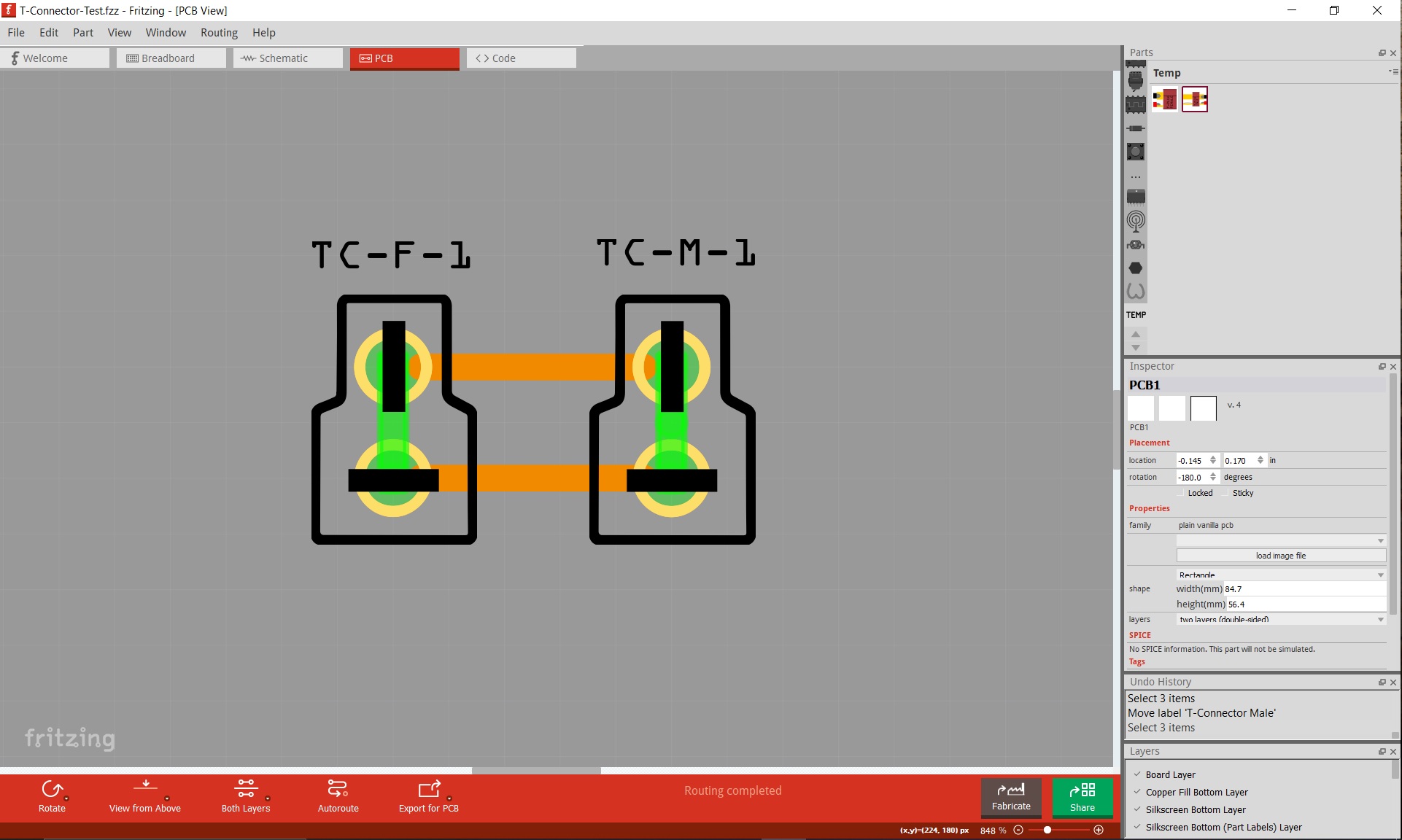
note the wire connects to the middle of the pin rather than the end as it should. In turn that means that the end of the connector is not on the 0.1in grid as it should be but rather is in the center of the pin. As well the schematic symbol should probably look like the male and female headers rather than the physical part. In PCB it would be more practical to have a circle (as with the headers) which a wire will connect in to. As well the part doesn’t pass DRC (routing->design rules check) as it thinks there is an overlap although the gerber output indicates there shouldn’t be one. That may be translates in the pcb svg.
As noted this layout isn’t practical because the actual connection would be a wire from the actual connector to the board which needs a circular pad like the header. If you haven’t seen them, these tutorials on parts making may help
note pcb has changed to pads with a hole size suitable for 12ga wire (I don’t necessarily expect anyone to use this, but if they want to it is there!) If you unzip the two .fzpz files you can see the changes I made to do this. As well schematic has the correct terminalIds and thus aligns to the grid and connects correctly to the wires.
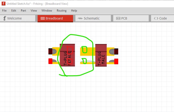
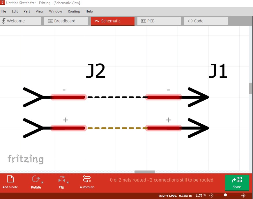
Using your tweaks, I have managed to get it how I wanted in the Breadboard view with the plug ‘linking’ upon ‘sliding’ them together - so when they are together correctly, a ‘green’ link is showing full connection. ( Must be some hidden XML code there ? )
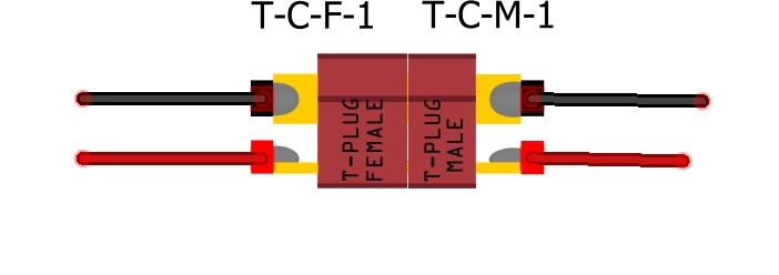
Have modified the T-Plug Schematic to show it more accurately ( as per IEC convention ) - seems to work Ok. May need to redefine where the wire link attaches to the ends ?
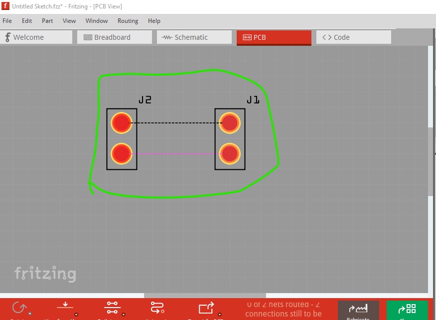
There is still an error with the placement of a plug onto a PCB layout, ( it should be in ‘end on’ form ) which will also need the cutout to suit the actual plug pins ( rectangular ) for it to fit the board correctly. The pads on the PCB surrounding the T-plug pins would also need to be substantial to enable soldering. I propose to change them to rectangular, with a required cutout to suit the pin. Still have a problem with the Copper layers also, as I couldn’t get it to work.
Follow the link for an example of T-Plug board mount : Charging Board …
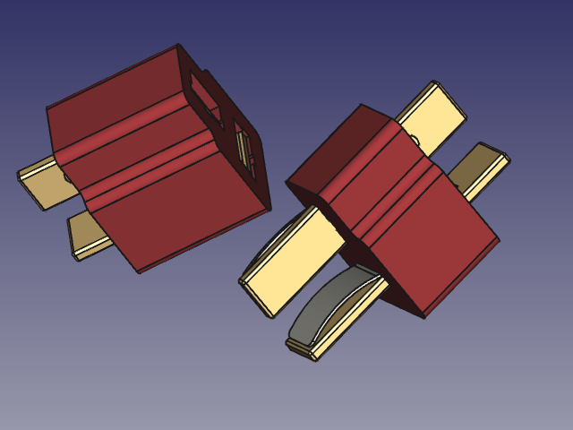
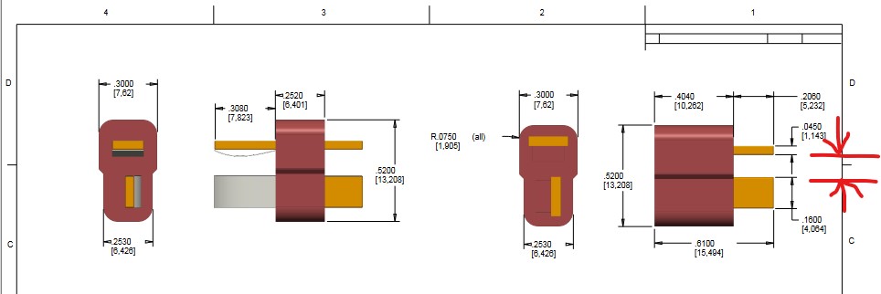
Fritzing doesn’t support slots in parts only holes. In order to get slots on a board you need to use a cutout (which applies the entire pcb) and make a custom svg for the outline for each instance (which is a major pain!) I see that the current holes won’t work (the pin is a bit larger than 4mm by 1mm from this Sparkfun spec sheet
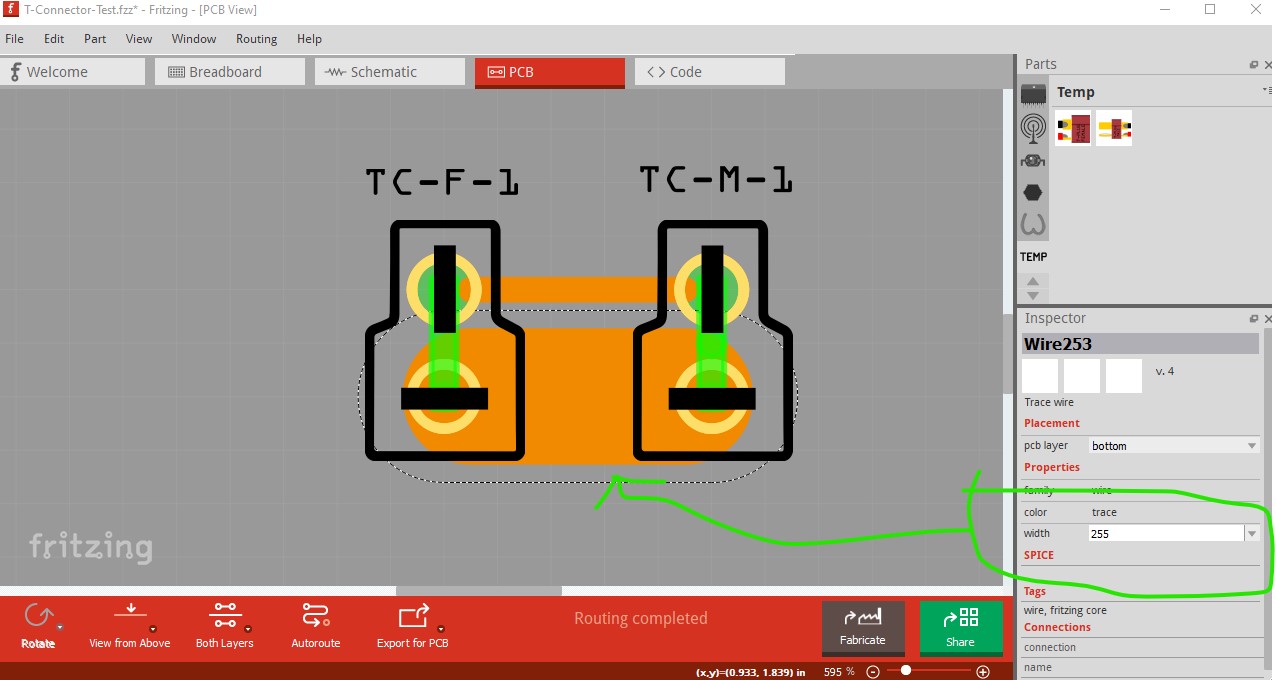
and a 4mm hole is likely to be hard to solder on the 1mm side and mechanically weak. I suspect there currently isn’t a good solution for this in Fritzing as the cutout method to get slots is going to be a real pain creating a suitable svg is difficult and would need to be done for each sketch. It is likely possible, just not anywhere near easy. An enhancement to allow slots in parts may be possible (it would need changes in the gerber processing), but I don’t think it is on the current roadmap at present. Trace size isn’t a problem, the ring thickness can be increased by increasing stroke-width on the pad and the trace will accept a typed size up to 255 in the trace size in the Inspector window, but there is still the problem with the hole not being able to be a slot.
Ok - Will experiment a little more on the PCB ‘square hole’ idea & look to make a rectangular pad large enough with hole to suit T-plug. …
P.S. - The trace layer only needs to be on one side … ( back or lower ) So it should be on layer copper0 ? and I don’t need to include the top copper layer …
I was going to make one as an example (because it is fairly complex) but I can’t find complete data sheet for the connector. The Sparkfun one above lacks one critical dimension and I can’t find any other datasheet (in fact the Sparkfun one is pretty much it!) that has it. There is no indication of what the spacing between the pins is which is required to make a footprint.
edit: I assumed that your pcb layout is correct (as the pads look to be about the right size for the slots) and went from there. First I created an outline svg (which I am lousy at ) using SVG path visualizer to manually modify the path to make Fritzing happy. It needs to be a single path that is differential (look for cutouts in the forum search bar to find previous articles on doing this.) That results in this svg (right click on it and save file as to get the svg!)
The two cutouts should fit the connector and will be milled. You need to copy the two slots and move them to the appropriate places to get more connectors (as noted before this will be painful!) to add more connectors. Then I modified your female plug to add oversize copper pads (larger by 0.04in than the pads in pcb) in this part
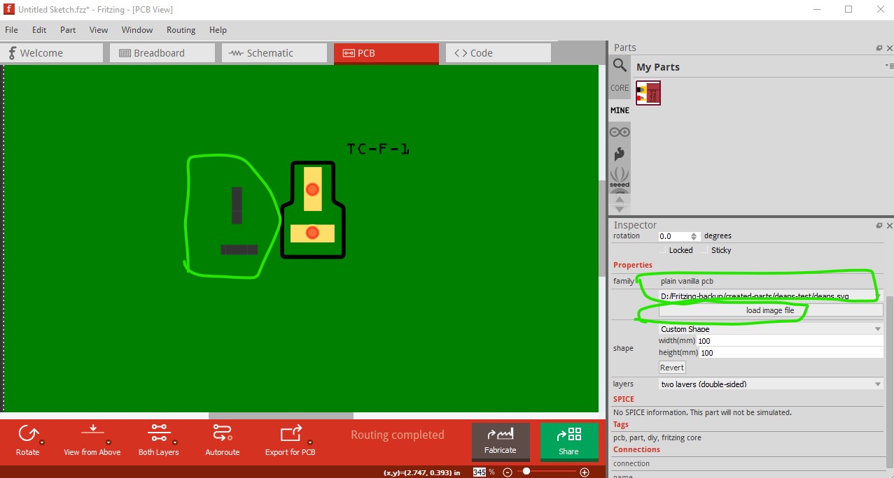
select the pcb grey backgound and then click load image file and feed it deans.svg. As you see that produces the green backgound (which will be the size of the board) and the two slots which will (hopefully) be milled in to the board. Now move the connector part over top of the slots and export the result as gerber files, then display them in gerbv
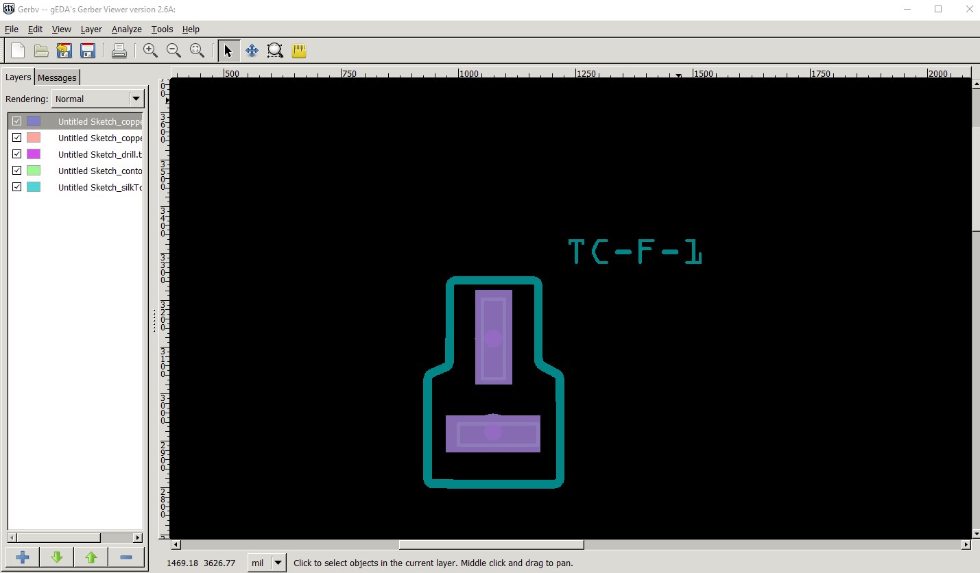
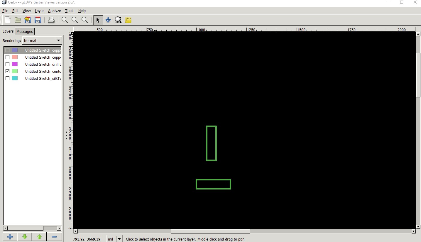
This is all five layers (copper0, copper1, drill, silkscreen and contour) You see the slot is almost aligned with the copper over lapping the milled slots (I think the slots should plate through as well, but I’m not sure!) Here is just the contour layer with the slots:
This is the only way I know of to get rectangular slots in Fritzing (and note I have not tried boards with this so I’ only assuming it will work!) Because you need to position the slots in the outline svg and then place the parts on them it is a tremendous pain in the ass, but I think it should work. Maneuvering the outline svg will be another pain probably easiest done by manually editing the path with a text editor. The deans.svg file is scaled so drawing units are 1thouandth of an inch so sizes in the path are in thousandths which makes things somewhat easier. It needs to be all a single differential path so the slots need to stay in the order they are in the file, if you change the path order the path won’t render the slots correctly in Fritzing.