vco.fzz (69.8 KB)
Thank you very much for your reply, sorry for the lack of printing, I just wanted to practice redoing modulars that I didn’t expect to get into this obscure part. I managed to modify the .fzpz to modify its spice code with gemini. I had several attempts which showed me that it affected something. I think the error described is not the right one. I would say that my problem is that I can’t spice this DC40106 with the oscillator in debug mode.
OK for me on Fritzing-1.0.6 there are a couple of errors in your .fzz file. The 1n4148 doesn’t appear to be found (if it is a custom part it should be in the.fzz file although I have not checked that)
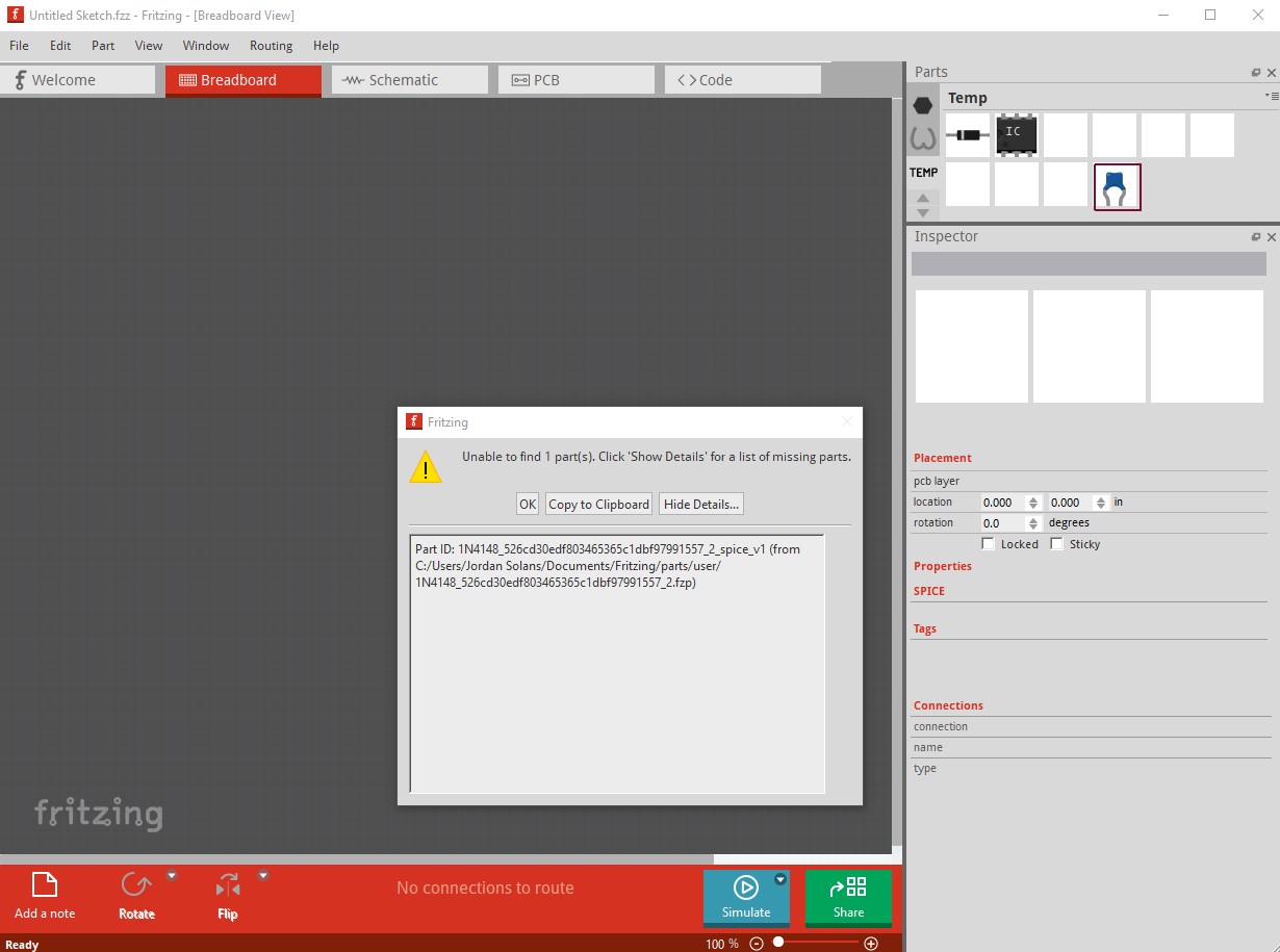
click OK to clear that and the .fzz file loads but when I hit simulate I get an error message that looks like this
The simulator gave an error when loading the netlist. Probably some SPICE field is wrong, please, check them.
If the parts are from the simulation bin, report the bug in GitHub.

Errors:
stdout Note: No compatibility mode selected!
stdout Circuit: simulator netlist
stderr Error: no such function 'if'
stderr Error: no such function 'if'
stderr Error: no such function 'if'
stderr Error: no such function 'if'
stderr Error: no such function 'if'
stderr Error: no such function 'if'
stderr Error on line:
stderr b.x1.b_out 13 8 v= if ( v(14) >   7.0000000000e-01 * v(1) ,   0.0000000000e+00 , if ( v(14) <   3.0000000000e-01 * v(1) , v(1) ,   5.0000000000e-01 * v(1) ) )
stderr parameter value out of range or the wrong type


Netlist:
Simulator Netlist
* Oscilloscope, com probe connected to 0 and voltage probes connected to 3, 10, 9 and 11
R2 0 3 100k
VBAT3 0_BAT3_aux 1 DC 9V
RBAT3 0_BAT3_aux 0 0.1
X1 14 13 1 8 schmitt_inverter
X2 12 11 1 8 schmitt_inverter
X3 10 9 1 8 schmitt_inverter
X4 6 5 1 8 schmitt_inverter
X5 4 3 1 8 schmitt_inverter
X6 2 1 1 8 schmitt_inverter
VBAT4 2_BAT4_aux 0 DC 9V
RBAT4 2_BAT4_aux 2 0.1
C2 3 0 2.2n IC=0
D3 4 3 DI_1N4001


    .SUBCKT schmitt_inverter IN OUT VDD VSS
    R_in IN VSS 1G
    B_out OUT VSS V = IF(V(IN) > 0.7*V(VDD), 0, IF(V(IN) < 0.3*V(VDD), V(VDD), 0.5*V(VDD)))
    .ENDS schmitt_inverter


*SRC=1N4001;DI_1N4001;Diodes;Si;  50.0V  1.00A  3.00us   Diodes, Inc. diode
.MODEL DI_1N4001 D  ( IS=76.9p RS=42.0m BV=50.0 IBV=5.00u CJO=39.8p  M=0.333 N=1.45 TT=4.32u )

.option savecurrents
.option interp
.OP
*.TRAN 1ms 100ms
* .AC DEC 100 100 1MEG
.END
Replacing the diode with the 1n4001 from the sim parts bin gets a similar error for me:
The simulator gave an error when loading the netlist. Probably some SPICE field is wrong, please, check them.
If the parts are from the simulation bin, report the bug in GitHub.

Errors:
stdout Note: No compatibility mode selected!
stdout Circuit: simulator netlist
stderr Error: no such function 'if'
stderr Error: no such function 'if'
stderr Error: no such function 'if'
stderr Error: no such function 'if'
stderr Error: no such function 'if'
stderr Error: no such function 'if'
stderr Error on line:
stderr b.x1.b_out 13 8 v= if ( v(14) >   7.0000000000e-01 * v(1) ,   0.0000000000e+00 , if ( v(14) <   3.0000000000e-01 * v(1) , v(1) ,   5.0000000000e-01 * v(1) ) )
stderr parameter value out of range or the wrong type


Netlist:
Simulator Netlist
* Oscilloscope, com probe connected to 1 and voltage probes connected to 4, 12, 11 and 13
R2 1 4 100k
VBAT3 1_BAT3_aux 2 DC 9V
RBAT3 1_BAT3_aux 1 0.1
X1 14 13 1 8 schmitt_inverter
X2 12 11 1 8 schmitt_inverter
X3 10 9 1 8 schmitt_inverter
X4 6 5 1 8 schmitt_inverter
X5 4 3 1 8 schmitt_inverter
X6 2 1 1 8 schmitt_inverter
VBAT4 3_BAT4_aux 1 DC 9V
RBAT4 3_BAT4_aux 3 0.1
C2 4 1 2.2n IC=0
D4 0 4 DI_1N4001


    .SUBCKT schmitt_inverter IN OUT VDD VSS
    R_in IN VSS 1G
    B_out OUT VSS V = IF(V(IN) > 0.7*V(VDD), 0, IF(V(IN) < 0.3*V(VDD), V(VDD), 0.5*V(VDD)))
    .ENDS schmitt_inverter


*SRC=1N4001;DI_1N4001;Diodes;Si;  50.0V  1.00A  3.00us   Diodes, Inc. diode
.MODEL DI_1N4001 D  ( IS=76.9p RS=42.0m BV=50.0 IBV=5.00u CJO=39.8p  M=0.333 N=1.45 TT=4.32u )

.option savecurrents
.option interp
.OP
*.TRAN 1ms 100ms
* .AC DEC 100 100 1MEG
.END
As before I don’t know enough to tell what is wrong, but something seems to be (I would guess something in the inverter spice model, but I don’t know for sure.) Interesting, I exported the in4148 diode from the temp parts bin (which Fritizing got from the .fzz file) and it appears to be complete when I unzipped it.So there is something odd going on here I expect but I am not sure what I still suspect the CD40106B but may well be wrong.
Peter
yes for The 1n4148 i know i change spice but im not sure he is good, but my probleme its th cd40106 because its im i change spice now and i thinking he dont simulate good he dont use the fonction trigger of schmit after for the diode him to i change spice so forget diode its possible the 40106 dont show the error windows but him dont have fonction
if i get there i think its possible to spice all of list for do simulation and prototype of vco
Hi,
Ngspice does not support the if function by default, but you can use the pspice compatibility mode to enable it.
Check the instructions at the end of this thread: https://www.google.com/url?sa=t&source=web&rct=j&opi=89978449&url=https://forum.fritzing.org/t/i-need-am-lm317-hv-with-spice/26648&ved=2ahUKEwick9DklMWQAxV5IhAIHQ2UADkQFnoECBsQAQ&usg=AOvVaw2Hq3fPOiR0ejZHohbCIaFU
Basically, you need to create a file in your user directory.
I do a lot of synth development but don’t do simulation for most of it since emulation is usually not accurate any way.
All the cmos stuff (and also XR2206, for instance) I do on breadboard first. Which is why I use fritzing in the first place.
I do sometimes use https://www.falstad.com/circuit/ to do some simulation, but it’s very rarely close to real life components. I’ve used Altium for smd/smt designs and there you get much closer, but it doesn’t really get you where doing actual bread board work (or solder) will get you.
The reason I mention this at all is that one recent design ( GitHub - poetaster/candelabra: Candelabra is a fritzing project and PCB gerbers for a Eurorack chaos CV generator using rotating color LEDs. ) which is a chaotic VC generator you can’t model with generic LED models and the actual behaviour of the LEDs that are used has to be obtained by measurements. The manufacturer only gives ‘vague’ values for forward voltage under a narrow set of conditions. To get a complete model would take so much time that it makes much more sense to just bread board it. Even altium won’t simulate this very simple circuit correctly.
If you want to do basics with hex schmitt triggers and the like, it’s much more fun on bread board.
1 Like
LTC1060.fzpz (7.9 KB)
1 Like
This just an example of functional spice simulation? Or is this the analog dual cap filter part?