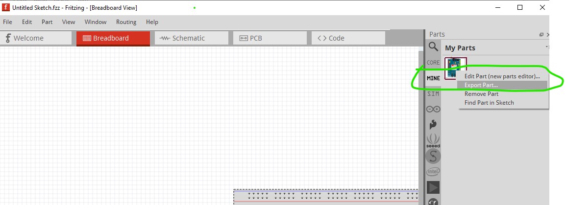
I thought it may be, Inkscape alone is a big learning curve let alone the rest of it. If you would upload the .fzpz file that parts editor produced with your changes I will add them to the schematic svg. To get the fzpz file click on the part in your mine parts bin and export it like this:
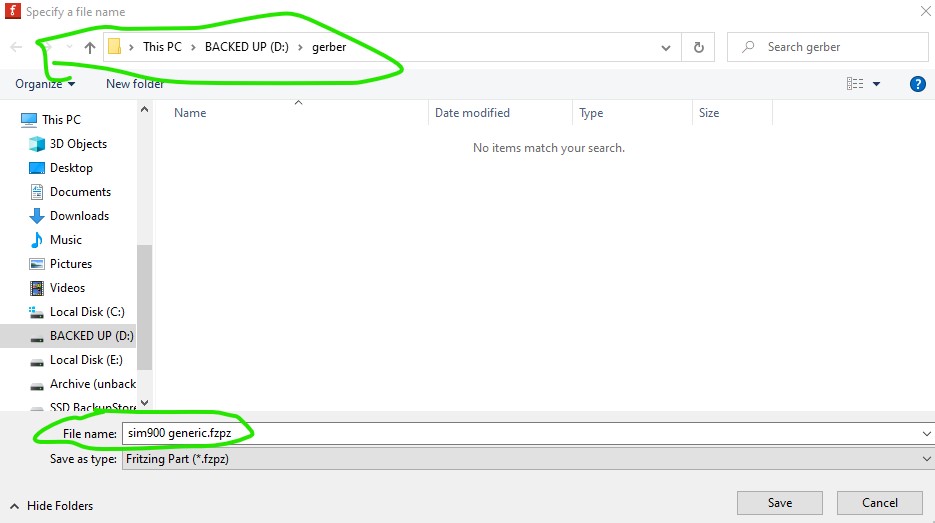
change the path to where ever you like and the file name if you wish then upload the .fzpz file from the file system. That will give me all the names that you changed to modify the schematic svg so it matches.
I’m starting to go crazy with this part and giving up. I had saved my changes with the names on the pins. No – I thought I saved. I then changed the SVG. That was easy. But when I reZIP and reload the file, the old schematic symbol with the wrong names continues to appear. I can’t upload the modified SIM900 because the program always says that a version is already loaded. But you can only see it if you search for SIM900 in the search field. And it cannot be deleted. Then I uninstalled the entire program and reinstalled it. But my secured SIM900 was gone or had incomplete content and could no longer be used. Over 8 hours of work for nothing
Unfortunately frustration is a common outcome in parts making. The odd (and undeleteable) outcome likely came from answering yes to one save parts? question and no to the next one. That will cause this. Your best bet is always to export the .fzpz file from the bin in to the file system where it is out of Fritzing’s control. Then you can reload (with varying amounts of work) the part. That said a reload of the program shouldn’t have affected the saved parts bins (they are specifically saved in special directories that are not modified by the install!) I’ll make the changes you listed and replace the current part in a bit. If you run in to the "already loaded"problem I can tell you how to get around it.
edit:
OK I have made all the changes (hopefully correctly) and will replace the part in the original post above with the corrected part. If Fritzing still complains about “part already loaded” when you try and load the new part, post and I will tell you how to clear it. The main changes are these
current
33 PD0/D0/RX/MTX0
34 RX serial select
35 PB0/D8/SRXD
36 PD1/D1/TX/MRX0
37 TX serial select
38 PD7/D7/STX0
new
33 PD7/D7/TX
34 TX serial select
35 PD0/D8/TX
36 PD8/D8/RX
35 RX serial select
36 PD1/D1/RX
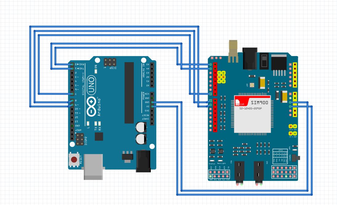
on the way by I changed all the arduino pins to the PDx format from what it was and removed the ? from the 3 top pins (leaving them as top1, top2 and top3.)
It works and it seems all to be correct. Now I must learn to create and modify parts. Fritzing has some strange behavior with some things
The jumperfield is correct now.
Do you know a really good tutorial? I found a lot on YouTube. But not really good. Mostly only for simple beginners, how to create a little example like blink-LED etc.
Thank you. But I don’t find any videolink in the posting. Only description of the videcontents with timelineexplanation when the part of the video would show this described elements.
But no link or embeded HTML-Video. Nothing to see. ???
You are right there don’t appear to be links to the videos. They are still there though, a google search for “Fritzing Part Creation - Chapter1 - New Part Editor” turns up the videos on youtube and it has links to the rest of the videos it looks like. The post is fairly old (5 or 6 years now) so something may have changed.