Hi folks,
I’m not sure, if the post belongs here or some other category, if wrong, please notify me and move it.
I built a word clock and wanted to create an own PCB for it.
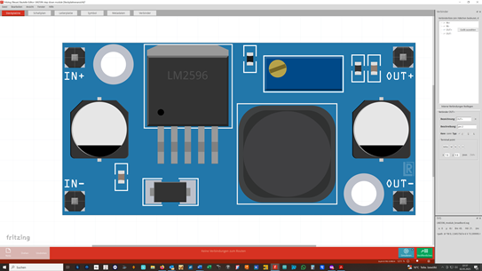
For the power supply I used a DC-DC step down buck converter, here the LM2595 DC-DC buck converter. For my layout I decided the fritzing part from “Robby”, the “LM2596 step down module”.
I routed the PCB and sent it to Aisler to get 9 PCB’s done, which I received wednesday.
After soldering I found out, that there is no function at all.
As being a present, I had to switch back to an experimental board, which worked at the first spot.
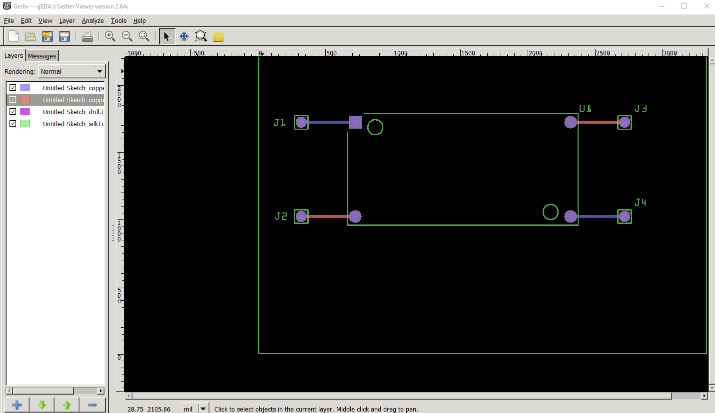
I took some time today trying to find the problem and found, that there is a problem with the layout from Robby. There are two pins switched: V out+ is where V out - should be and otherwise.
The part itself look the way it should:
but the pins are dfinitely changed

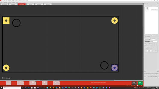
The rest ist working, but the PCB’s are completely useless, cause I have a double layer with copperfilling for ground.
First: Does anybody check the layouts, before they are given to the crowd?
Second: How can I change the layout to eliminate the problem, cause I want to build some more of the clocks with my PCB layout.
Third: I’m pretty upset, cause I ruined around 50€ and quite a day finding the problem.
Is there some help for me?
THX in advance!
Freddie