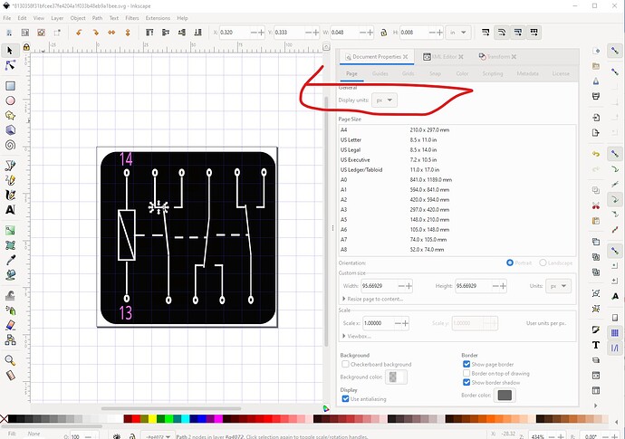
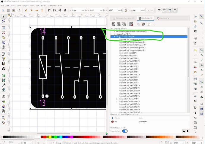
The upload worked fine. The forum renders the uploaded svg, and if you right click on the image and select save image as it will download the svg. That said the svg format is incorrect for breadboard and has a number of extra (and likely unwanted!) connectors. The layout is more usual for the schematic svg, breadboard is usually an image of the part with the connectors specified. The svg is set to be an incorrectly formatted pcb svg though (it has copper layers which are not used in breadboard) and is dimensioned in px which usually causes scaling issues.
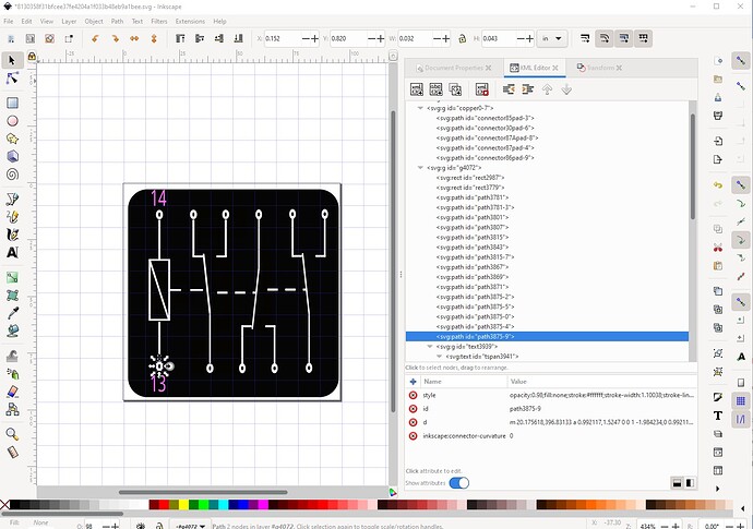
The units wants to be in inches or mm not px. Fritzing will guess which of 72DPI or 90DPI is in use and sometimes get it wrong. In addition current Inkscape is using 96DPI which will make the scale almost certainly wrong. For breadboard you likely want the connectors to start at connector0pin and go up in sequence starting at the bottom left pad:
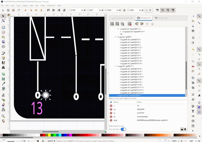
it should preferably be a circle rather than a path (although either will actually work) like this:
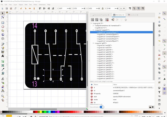
parts editor is likely reacting to the various (incorrect) connector definitions like this one:
which is likely the cause of your unexpected images. The breadboard svg should have a layerId of breadboard like this:
These two sets of tutorials apply to current versions of Fritzing and may also help (I tend to not use parts editor but rather edit the underlying files, the video tutorials do tend to use parts editor though)
Peter
