Your svg files are not in the correct format and lack layerIds. FritzingCheckPart.py reports the following errors on your part.
$ FritzingCheckPartw.py ‘part.OPTOCOUPLER 4CH_53b951f7e12564af33ab05b3ac698a0f_10.fzp’
**** Starting to process file Startup, no file yet
**** Starting to process file part.OPTOCOUPLER 4CH_53b951f7e12564af33ab05b3ac698a0f_10.fzp
**** Starting to process file svg.breadboard.OPTOCOUPLER 4CH_2d7194bb8fdbc56d8a7c9b6c0e392041_3_breadboard.svg.bak
**** Starting to process file svg.schematic.OPTOCOUPLER 4CH_2d7194bb8fdbc56d8a7c9b6c0e392041_3_schematic.svg.bak
**** Starting to process file svg.pcb.OPTOCOUPLER 4CH_2d7194bb8fdbc56d8a7c9b6c0e392041_3_pcb.svg.bak
File
‘part.OPTOCOUPLER 4CH_53b951f7e12564af33ab05b3ac698a0f_10.fzp.bak’
This is a through hole part as both copper0 and copper1 views are present.
If you wanted a smd part remove the copper0 definition from line 50
Modified 4: File
‘svg.breadboard.OPTOCOUPLER 4CH_2d7194bb8fdbc56d8a7c9b6c0e392041_3_breadboard.svg.bak’
At line 4
ReferenceFile
‘OPTOCOUPLER X4.svg’
doesn’t match input file
‘OPTOCOUPLER 4CH_2d7194bb8fdbc56d8a7c9b6c0e392041_3_breadboard.svg’
Corrected
Modified 4: File
‘svg.schematic.OPTOCOUPLER 4CH_2d7194bb8fdbc56d8a7c9b6c0e392041_3_schematic.svg.bak’
At line 4
ReferenceFile
‘OPTOCOUPLER X4 SCH.svg’
doesn’t match input file
‘OPTOCOUPLER 4CH_2d7194bb8fdbc56d8a7c9b6c0e392041_3_schematic.svg’
Corrected
Modified 4: File
‘svg.pcb.OPTOCOUPLER 4CH_2d7194bb8fdbc56d8a7c9b6c0e392041_3_pcb.svg.bak’
At line 4
ReferenceFile
‘OPTOCOUPLER X4 PCB.svg’
doesn’t match input file
‘OPTOCOUPLER 4CH_2d7194bb8fdbc56d8a7c9b6c0e392041_3_pcb.svg’
Corrected
Warning 6: File
‘part.OPTOCOUPLER 4CH_53b951f7e12564af33ab05b3ac698a0f_10.fzp.bak’
At line 2
ReferenceFile name
‘2-channel-relay-module_1.fzp’
Doesn’t match fzp filename
‘OPTOCOUPLER 4CH_53b951f7e12564af33ab05b3ac698a0f_10.fzp’
Warning 32: File
‘svg.breadboard.OPTOCOUPLER 4CH_2d7194bb8fdbc56d8a7c9b6c0e392041_3_breadboard.svg.bak’
At line 2
Scale is not the desirable 1/1000 ratio from width/height to
viewBox width/height.
Warning 23: File
‘svg.breadboard.OPTOCOUPLER 4CH_2d7194bb8fdbc56d8a7c9b6c0e392041_3_breadboard.svg.bak’
At line 22
Key -inkscape-font-specification
value ‘Droid Sans, Normal’ is invalid and has been deleted
Warning 32: File
‘svg.schematic.OPTOCOUPLER 4CH_2d7194bb8fdbc56d8a7c9b6c0e392041_3_schematic.svg.bak’
At line 2
Scale is not the desirable 1/1000 ratio from width/height to
viewBox width/height.
Warning 23: File
‘svg.schematic.OPTOCOUPLER 4CH_2d7194bb8fdbc56d8a7c9b6c0e392041_3_schematic.svg.bak’
At line 142
Key -inkscape-font-specification
value ‘OCRA, Normal’ is invalid and has been deleted
Warning 32: File
‘svg.pcb.OPTOCOUPLER 4CH_2d7194bb8fdbc56d8a7c9b6c0e392041_3_pcb.svg.bak’
At line 2
Scale is not the desirable 1/1000 ratio from width/height to
viewBox width/height.
Warning 20: File
‘svg.pcb.OPTOCOUPLER 4CH_2d7194bb8fdbc56d8a7c9b6c0e392041_3_pcb.svg.bak’
At line 30
copper1 layer should be at the top, not under group copper0
Error 69: File
‘svg.breadboard.OPTOCOUPLER 4CH_2d7194bb8fdbc56d8a7c9b6c0e392041_3_breadboard.svg.bak’
At line 21
Found a drawing element before a layerId (or no layerId)
Error 77: File
‘svg.schematic.OPTOCOUPLER 4CH_2d7194bb8fdbc56d8a7c9b6c0e392041_3_schematic.svg.bak’
At line 18
terminalId connector146terminal can’t be a g as it won’t work.
Error 77: File
‘svg.schematic.OPTOCOUPLER 4CH_2d7194bb8fdbc56d8a7c9b6c0e392041_3_schematic.svg.bak’
At line 19
terminalId connector147terminal can’t be a g as it won’t work.
Error 77: File
‘svg.schematic.OPTOCOUPLER 4CH_2d7194bb8fdbc56d8a7c9b6c0e392041_3_schematic.svg.bak’
At line 20
terminalId connector148terminal can’t be a g as it won’t work.
Error 77: File
‘svg.schematic.OPTOCOUPLER 4CH_2d7194bb8fdbc56d8a7c9b6c0e392041_3_schematic.svg.bak’
At line 21
terminalId connector149terminal can’t be a g as it won’t work.
Error 77: File
‘svg.schematic.OPTOCOUPLER 4CH_2d7194bb8fdbc56d8a7c9b6c0e392041_3_schematic.svg.bak’
At line 22
terminalId connector129terminal can’t be a g as it won’t work.
Error 77: File
‘svg.schematic.OPTOCOUPLER 4CH_2d7194bb8fdbc56d8a7c9b6c0e392041_3_schematic.svg.bak’
At line 23
terminalId connector130terminal can’t be a g as it won’t work.
Error 77: File
‘svg.schematic.OPTOCOUPLER 4CH_2d7194bb8fdbc56d8a7c9b6c0e392041_3_schematic.svg.bak’
At line 24
terminalId connector131terminal can’t be a g as it won’t work.
Error 77: File
‘svg.schematic.OPTOCOUPLER 4CH_2d7194bb8fdbc56d8a7c9b6c0e392041_3_schematic.svg.bak’
At line 25
terminalId connector132terminal can’t be a g as it won’t work.
Error 77: File
‘svg.schematic.OPTOCOUPLER 4CH_2d7194bb8fdbc56d8a7c9b6c0e392041_3_schematic.svg.bak’
At line 26
terminalId connector133terminal can’t be a g as it won’t work.
Error 77: File
‘svg.schematic.OPTOCOUPLER 4CH_2d7194bb8fdbc56d8a7c9b6c0e392041_3_schematic.svg.bak’
At line 27
terminalId connector144terminal can’t be a g as it won’t work.
Error 77: File
‘svg.schematic.OPTOCOUPLER 4CH_2d7194bb8fdbc56d8a7c9b6c0e392041_3_schematic.svg.bak’
At line 28
terminalId connector142terminal can’t be a g as it won’t work.
Error 77: File
‘svg.schematic.OPTOCOUPLER 4CH_2d7194bb8fdbc56d8a7c9b6c0e392041_3_schematic.svg.bak’
At line 29
terminalId connector143terminal can’t be a g as it won’t work.
Error 77: File
‘svg.schematic.OPTOCOUPLER 4CH_2d7194bb8fdbc56d8a7c9b6c0e392041_3_schematic.svg.bak’
At line 30
terminalId connector141terminal can’t be a g as it won’t work.
Error 77: File
‘svg.schematic.OPTOCOUPLER 4CH_2d7194bb8fdbc56d8a7c9b6c0e392041_3_schematic.svg.bak’
At line 31
terminalId connector140terminal can’t be a g as it won’t work.
Error 77: File
‘svg.schematic.OPTOCOUPLER 4CH_2d7194bb8fdbc56d8a7c9b6c0e392041_3_schematic.svg.bak’
At line 32
terminalId connector136terminal can’t be a g as it won’t work.
Error 77: File
‘svg.schematic.OPTOCOUPLER 4CH_2d7194bb8fdbc56d8a7c9b6c0e392041_3_schematic.svg.bak’
At line 33
terminalId connector151terminal can’t be a g as it won’t work.
Error 77: File
‘svg.schematic.OPTOCOUPLER 4CH_2d7194bb8fdbc56d8a7c9b6c0e392041_3_schematic.svg.bak’
At line 34
terminalId connector138terminal can’t be a g as it won’t work.
Error 77: File
‘svg.schematic.OPTOCOUPLER 4CH_2d7194bb8fdbc56d8a7c9b6c0e392041_3_schematic.svg.bak’
At line 35
terminalId connector137terminal can’t be a g as it won’t work.
Error 77: File
‘svg.schematic.OPTOCOUPLER 4CH_2d7194bb8fdbc56d8a7c9b6c0e392041_3_schematic.svg.bak’
At line 36
terminalId connector150terminal can’t be a g as it won’t work.
Error 77: File
‘svg.schematic.OPTOCOUPLER 4CH_2d7194bb8fdbc56d8a7c9b6c0e392041_3_schematic.svg.bak’
At line 37
terminalId connector134terminal can’t be a g as it won’t work.
Error 77: File
‘svg.schematic.OPTOCOUPLER 4CH_2d7194bb8fdbc56d8a7c9b6c0e392041_3_schematic.svg.bak’
At line 38
terminalId connector139terminal can’t be a g as it won’t work.
The reason pcb isn’t working correctly is that the .fzp file isn’t correct (and parts editor AFAIK won’t usually modify the fzp file, it needs to be copied from a part with the correct number of connectors to work.)
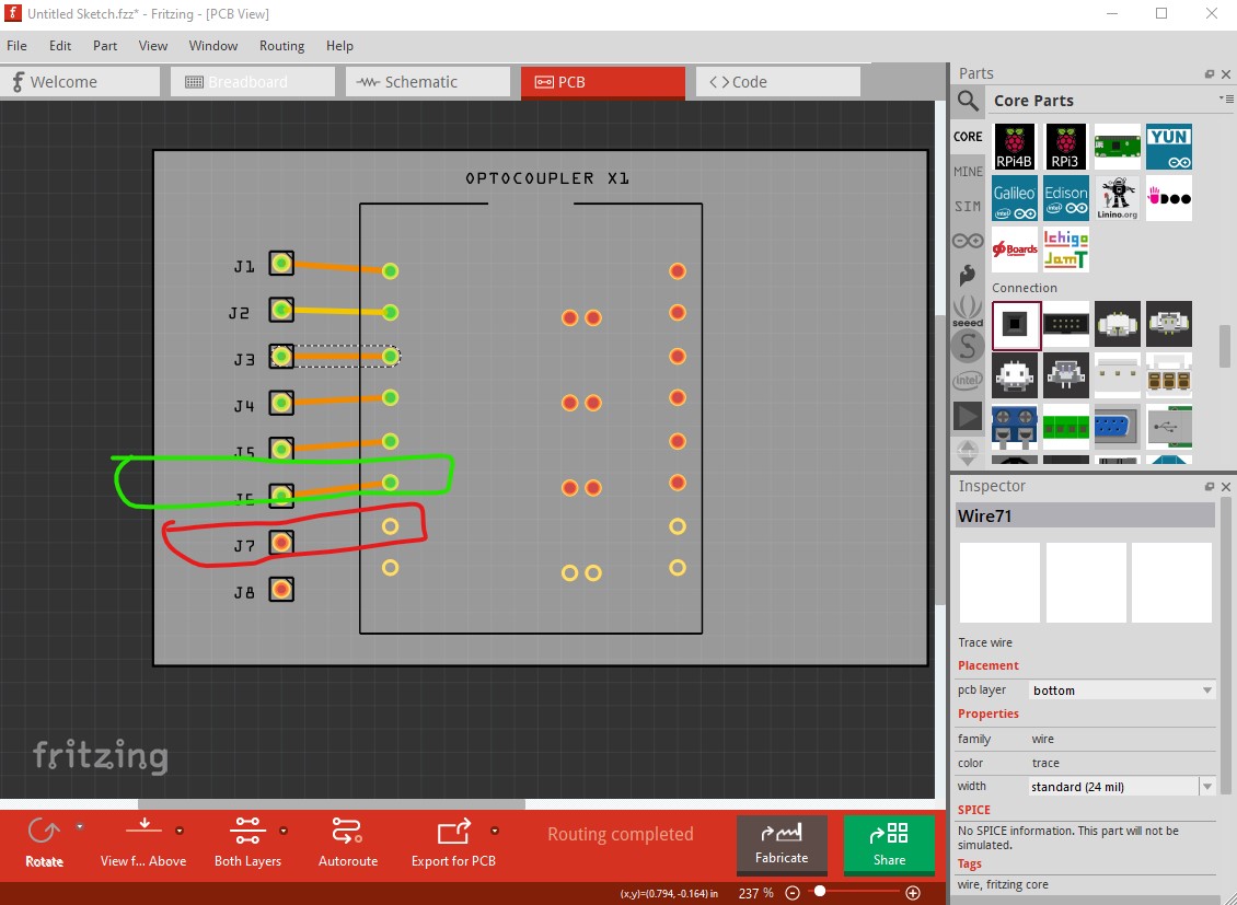
here we see connector5 works but connector6 doesn’t. The reason is this in the fzp file for the part, connector5 is properly defined with a pcb view defined so the pins work.
    <connector id="connector5" name="G" type="male">
      <description>GND</description>
      <views>
        <breadboardView>
          <p layer="breadboard" svgId="connector5pin"/>
        </breadboardView>
        <schematicView>
          <p layer="schematic" svgId="connector5pin" terminalId="connector5terminal"/>
        </schematicView>
        <pcbView>
          <p layer="copper0" svgId="connector5pin"/>
          <p layer="copper1" svgId="connector5pin"/>
        </pcbView>
      </views>
    </connector>
connector6 is has no pcb connection information and thus doesn’t work.
      <description>V+ IN TO LED CH4</description>
      <views>
        <breadboardView>
          <p layer="breadboard" svgId="connector6pin"/>
        </breadboardView>
        <schematicView>
          <p layer="schematic" svgId="connector6pin" terminalId="connector6terminal"/>
        </schematicView>
        <pcbView/>
      </views>
    </connector>
note pcb view in this entry is an empty group so the pins don’t work. The following tutorials on part making may help (I as you will see, typically don’t use parts editor as it wasn’t completed when development stopped in 2016 and hasn’t yet been finished.) I tend to directly edit the underlying files which I find much easier than fighting parts editor. Both of these tutorials apply to current versions of Fritizng many of the others are for older versions.
I lately learned there aren’t links to the videos in Old_Grey’s tutorial so you need to do a google search for the title and then they come up on YouTube.
Hope this helps, if not feel free to post again.
Peter