I created a svg file for my pcb view in Affinity Designer, and it’s in normal shape, in other viewers (e.g. Edge) as well. But when I import it into the parts editor, it looses it’s shape.
Upload the svg file and one of us will have a look at it. There are a variety of that could be wrong and it is hard to tell without the svg to look at. Upload is 7the icon from the left in the reply menu.
Peter
Thanks
![]()
The likely problem is the dimension information for the image. From the svg header element
width="100%" height="100%" viewBox="0 0 43 83"
Fritzing needs “real” dimensions with units. Normally “in” (inches) or mm". It does not know how to properly translate “100%” into actual dimensions. It needs an actually size to be able to scale properly to match the other parts it is using. The “43 83” does not help. That is not physical units either.
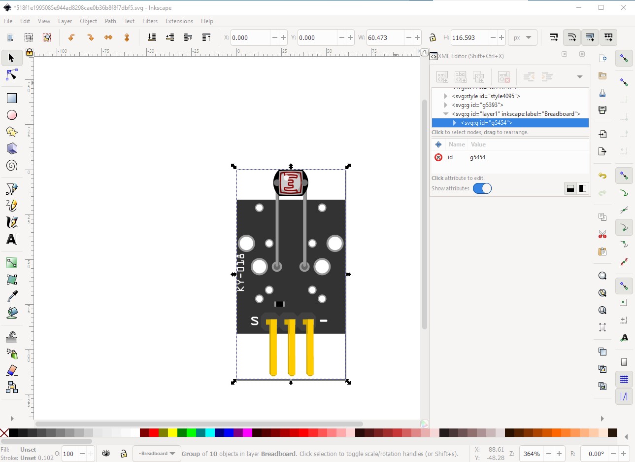
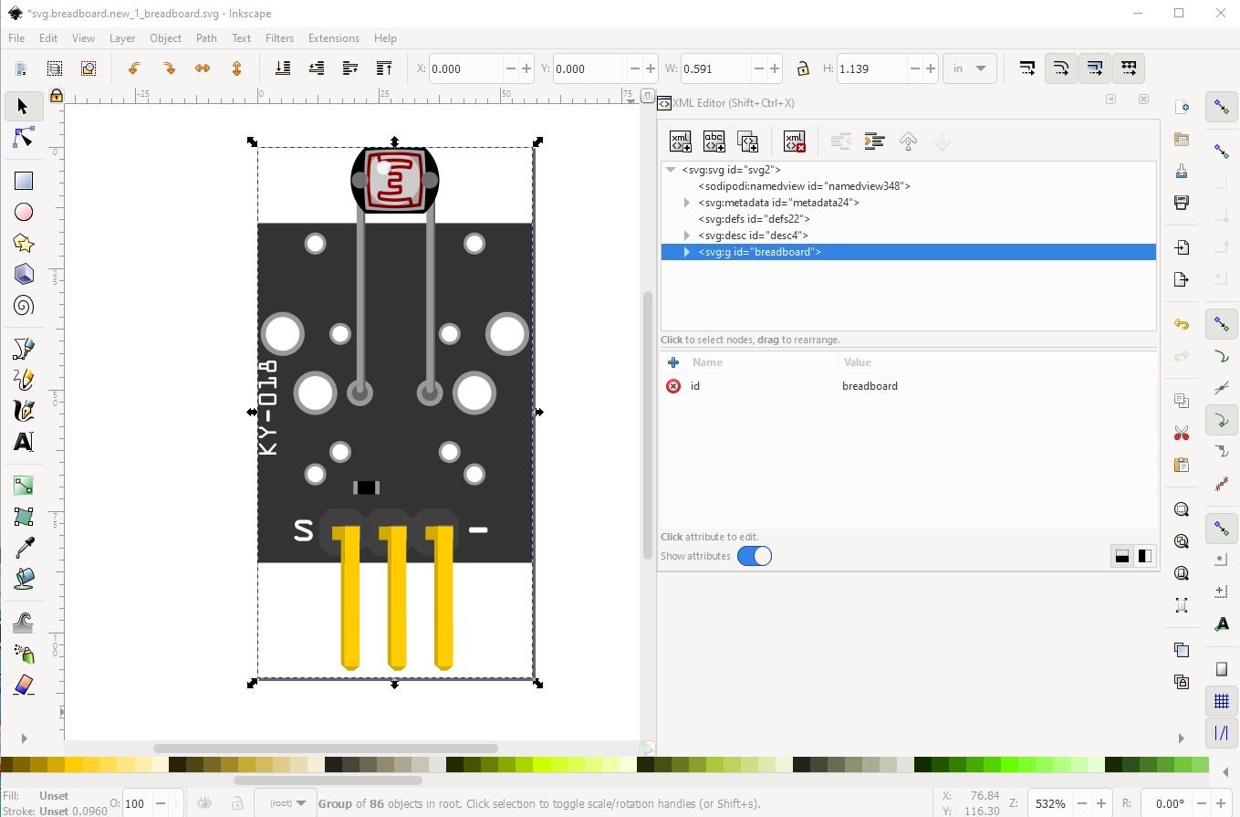
As @microMerlin said, the main problem is dimensions not in real world units. This is what the original svg looks like in Inkscape:
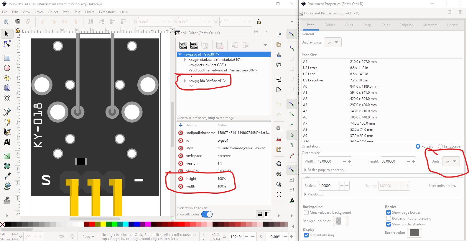
Note on the left size drawing dimensions are in px (which make them in drawing units which depend on the DPI setting.) This is bad because Fritzing will try and guess what the DPI was (72 DPI or 90DPI) and will often get it wrong (the current svg standard is 96DPI which Fritzing doesn’t recognize at all!) Inches or mm are a safer bet. As well the layerId is missing the top level group should be labeled breadboard (or whatever the layerId in the .fzp file is which is usually breadboard.) To fix this I ungrouped the svg, set the drawing units to in then selected the entire image and then did a resize image to selection to reset the units in the first line of the svg, then grouped the image and named it breadboard so it looks like this:
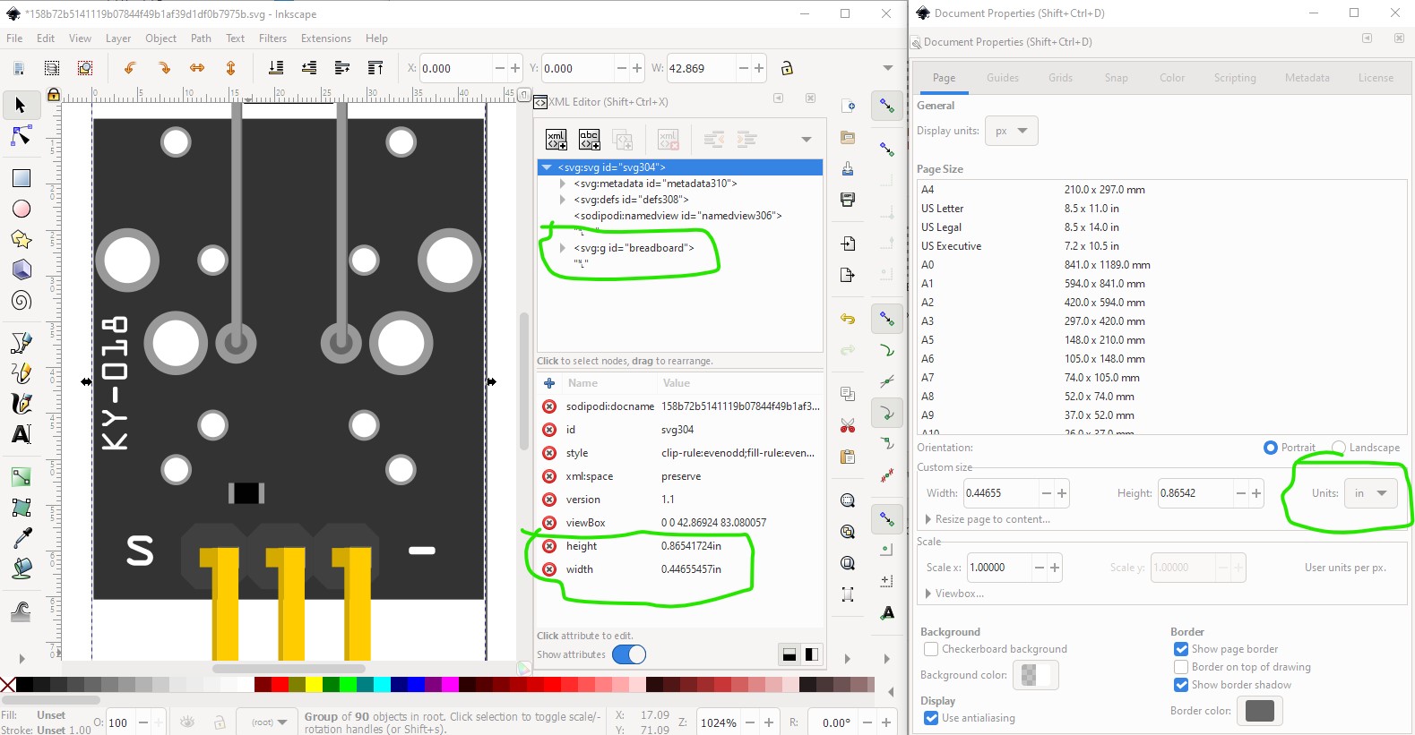
So this svg
![]()
from Inkscape should load correctly in to the parts editor.
Peter
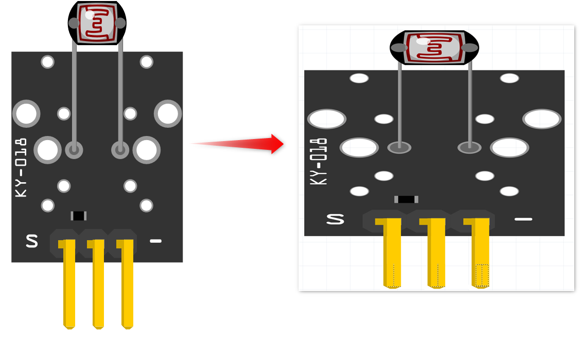
Hi thanks for your help. I tried to import it in fritzing, but the grid of the pins doesn’t fit.
I’m really frustrated now. Normaly I do vector graphics with Affinity Designer, because it offers some more features than Inkscape. But I tought I give it a try, and recreated the complete module in Inkscape and tried to keep all your hints in mind.
I used a buzzer module as template.
But now, i get some other errors when I try to import. It’s really annoying, i was so motivated to create some modules, because the design work is fun, but the fritzing side is (for me) a really big problem.
If you post your Inkscape svg I can probably figure out what Fritzing is unhappy about and how to fix it. These two sets of tutorials apply to current versions of Fritzing (most of the others are pre parts editor, I don’t usually use parts editor but edit the underlying files directly):
Peter
Thanks for your help.
Fritzing tries to be beginner friendly, but this part of the software is defeitely not beginnner friendly 

Parts Editor was ‘bolted on’ to the original Frtizing applications. I don’t think it was really completed. There are too many cases where it does not handle things that are documented to work in the parts file structure. Which is why several people creating parts edit the files manually. Both svg and fzp are xml files, which is normal text. Doing that is not beginner friendly either though. But it can do things that are just not possible with Parts Editor.
You seem to be getting caught by the difference between an image to be display and printed, and something that is intended to be use to accurately represent a physical part. ai (and Inkscape) are not really intended for use as cadd (computer aided design and drafting) applications. The svg file structure ‘supports’ cadd style drawings, but the applications do not enforce it, or make it easy. They lean toward creating things that look good on screen, without worrying about actual real world sizes. At least with Inkscape, it is possible to be compatible, by following a few process steps to get the needed units and dimensions into the images. I don’t know what is needed to get ai to do the same. I know that using percentages for size is not going to work well.
That is true, but it unfortunately a requirement to get the functionality in Fritzing. I expect they considered requiring expertise in making parts a reasonable trade off (although the parts editor which wasn’t finished when development died in 2016 was intended to make things easier) for ease of use. OK, there are a few problems (and an apparent bug) here. First as Fritzing notes your fonts are not correct. You may need to load the Fritzing fonts from
https://fritzing.org/learning/tutorials/creating-custom-parts/download-fonts-and-templates
and install them on your system so the correct versions are present.
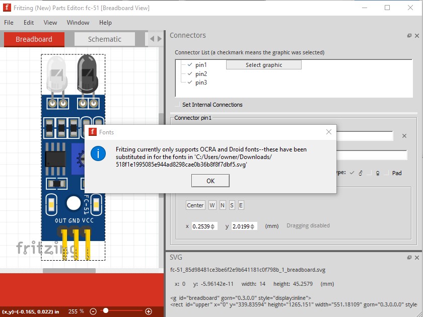
this isn’t harmful, it is just telling you that it substituted fonts. The next error however appears to be a bug in Fritzing.
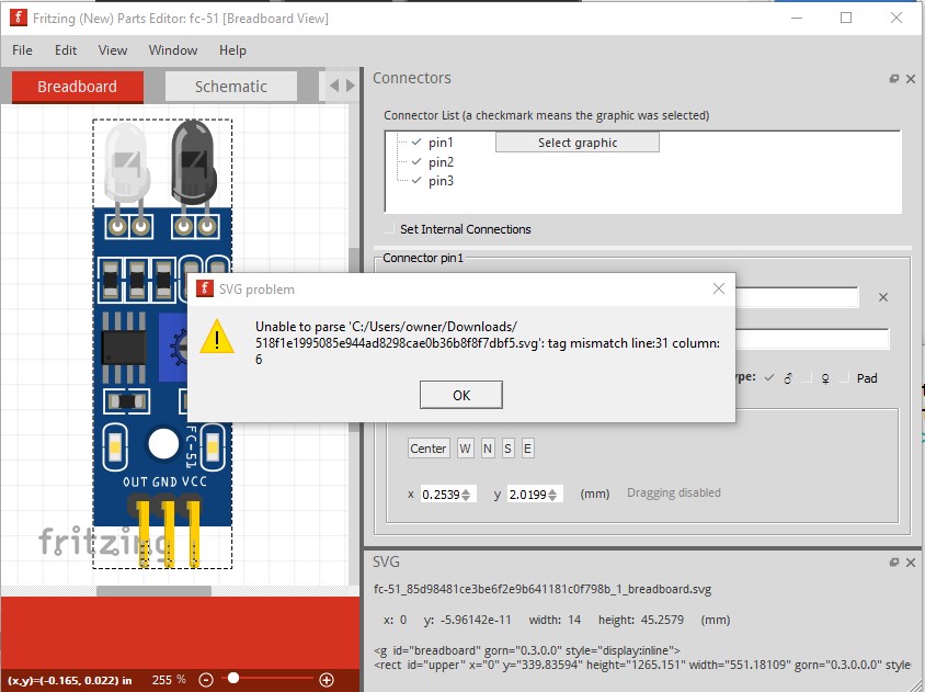
which I will report on github. FritzingCheckPart.py parses the svg without complaint indicating that it is valid xml
Warning 23: File
‘518f1e1995085e944ad8298cae0b36b8f8f7dbf5.svg’
At line 13
Key -inkscape-font-specification
value ‘OCR A Extended’ is invalid and has been deleted
Warning 24: File
‘518f1e1995085e944ad8298cae0b36b8f8f7dbf5.svg’
At line 13
Font family ‘OCR A Extended’ is not Droid Sans or OCRA
This won’t render in Fritzing
Error 69: File
‘518f1e1995085e944ad8298cae0b36b8f8f7dbf5.svg’
At line 12
Found a drawing element before a layerId (or no layerId)
Fritzing shouldn’t be complaining about the format, the missing layerId is a problem but that isn’t fatal (it will cause the part to not be exported as an image though.) As a fix I grabbed the fc-51 breadboard svg and deleted all content leaving me with a standard format svg
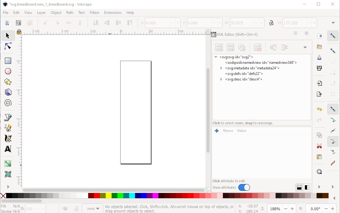
and then in the original svg did a copy of just the content in g5454 and pasted it in to the blank svg to remove the odd parts of the original svg.
original svg
new svg
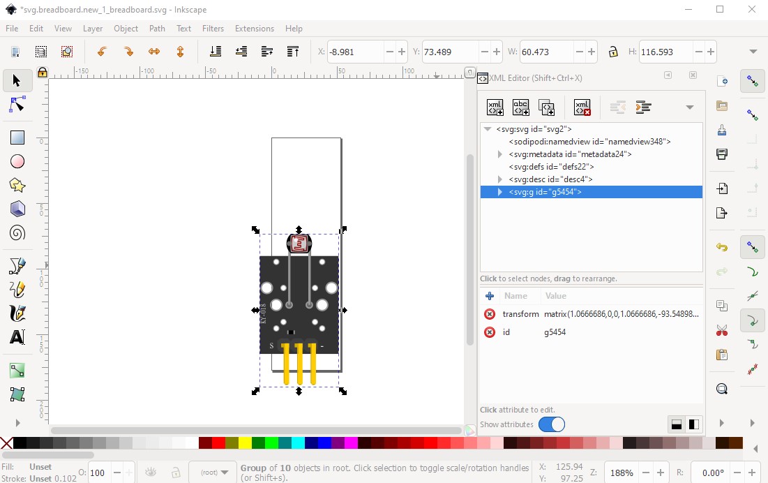
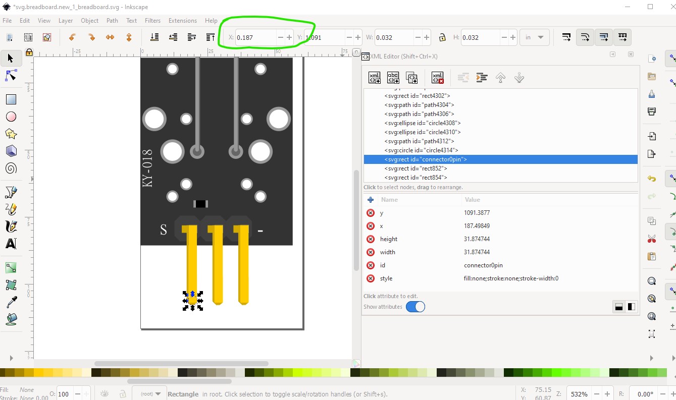
then I added a rectangle for the needed connector pin (fill=none stroke=none stroke-width=0)
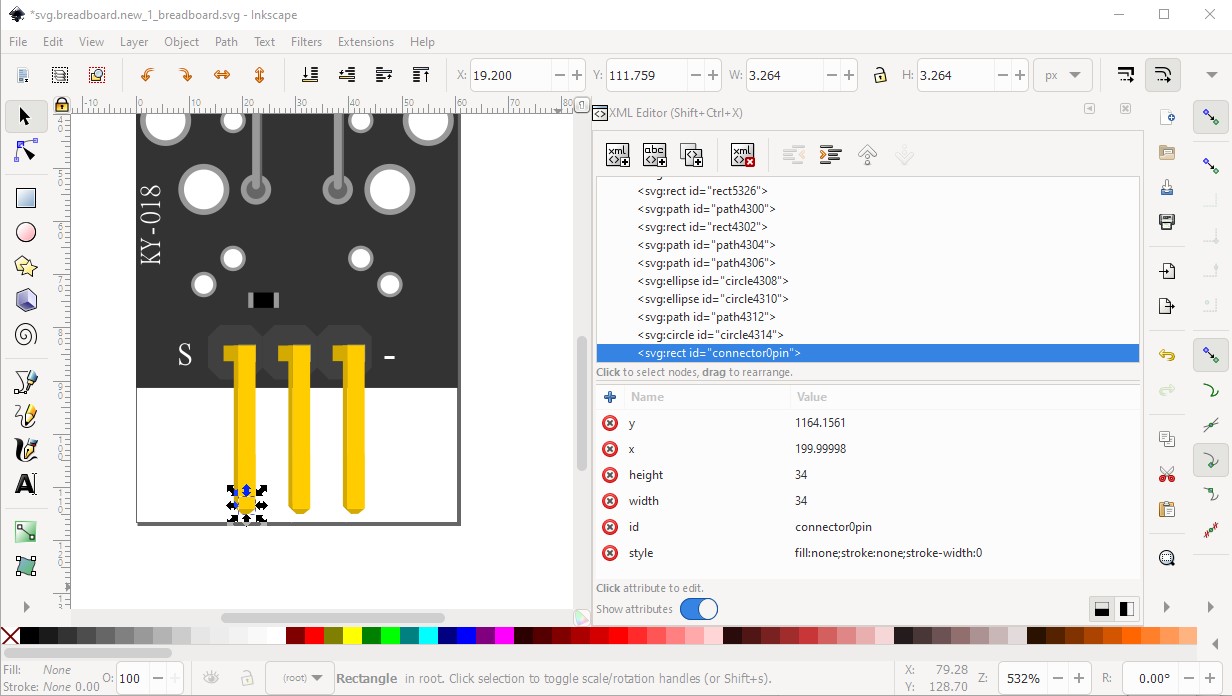
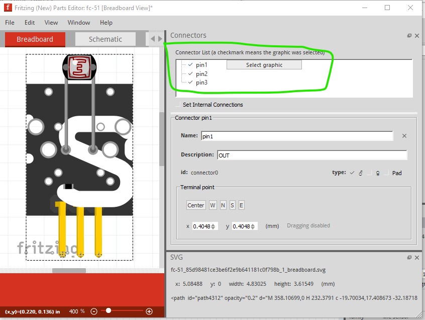
then duplicated it and moved it 0.1in in X, twice to create the other two connectors. That turns up a scaling error.
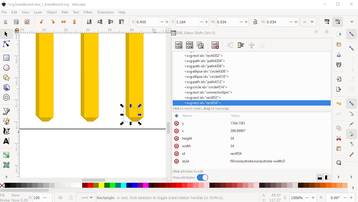
The end square needs to align with the end pin and be on a 0.1in boundary to match the default 0.1in grid in breadboard so the svg needs to be scaled down a bit until that is true.
found a part at
and copied in the breadboard file from that part to compare. It looks like your svg needs to be scaled down until the pins are on 0.1in boundaries (typically breadboard images are the same size as the real life part!)
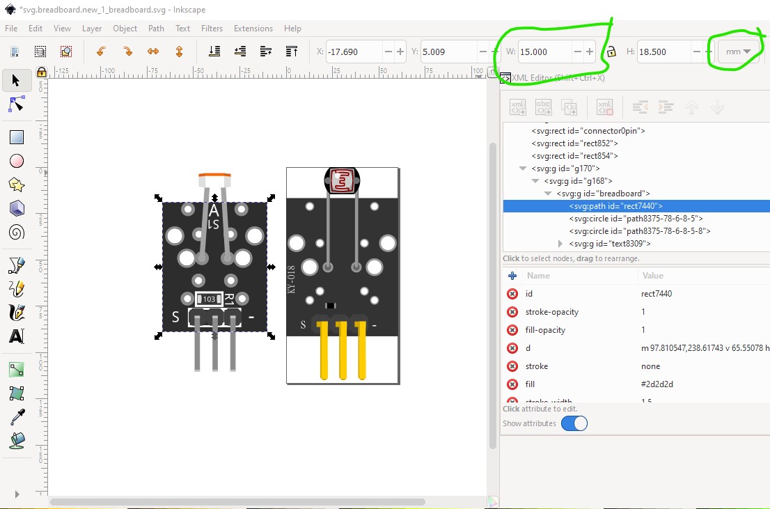
here we see the width of the part should be 15mm so I selected your part, then locked w to height and reduced width from 16mm to 15mm to rescape your part which should put the pins on the requred 0.1in boundaries.
to
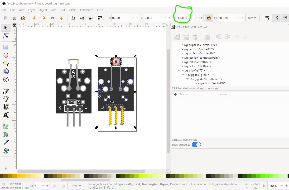
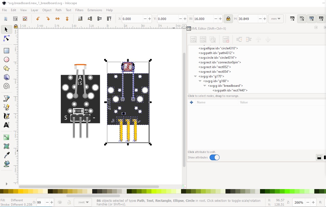
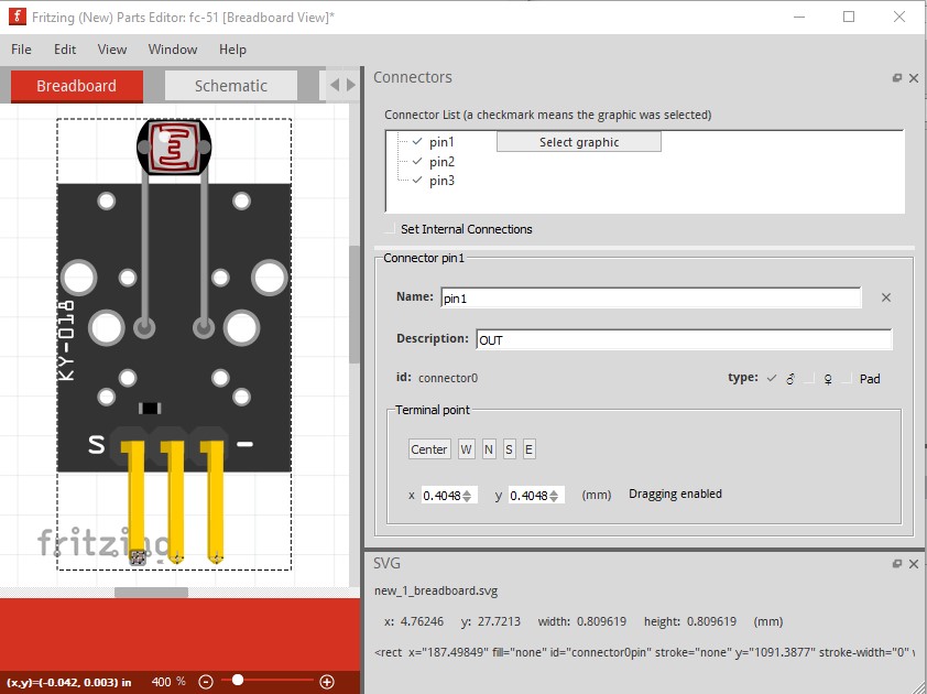
and indeed now the pin spacing is correct:
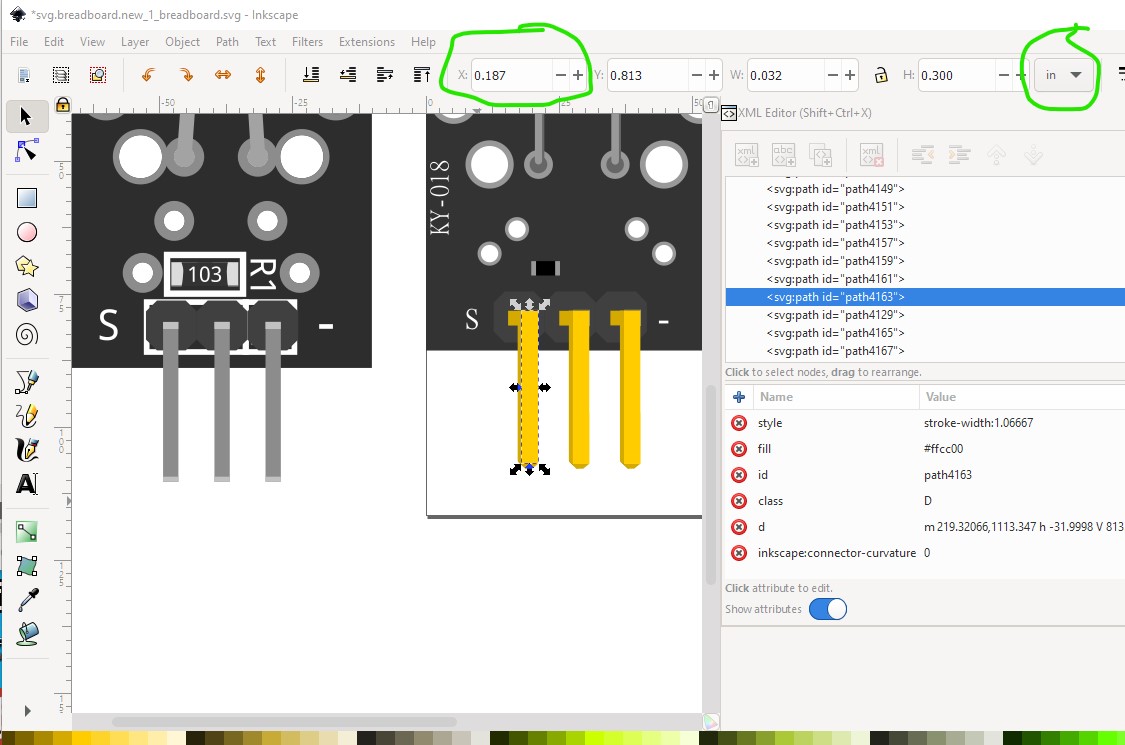
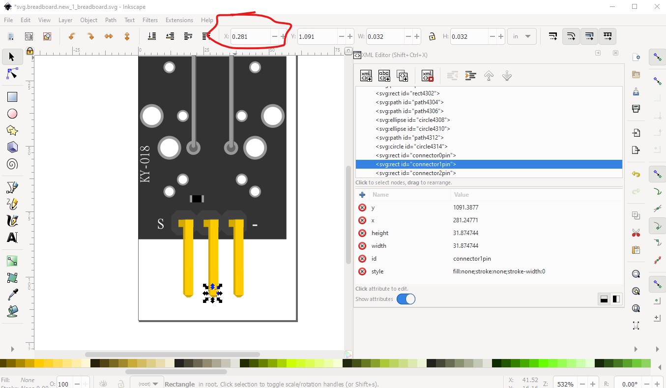
Now I need to adjust the x position of the connectors as the scale will have changed them (they were on 0.1in boundaries before the re scale and will be incorrect now!) Connector0pin is correct (aligned with its pin)
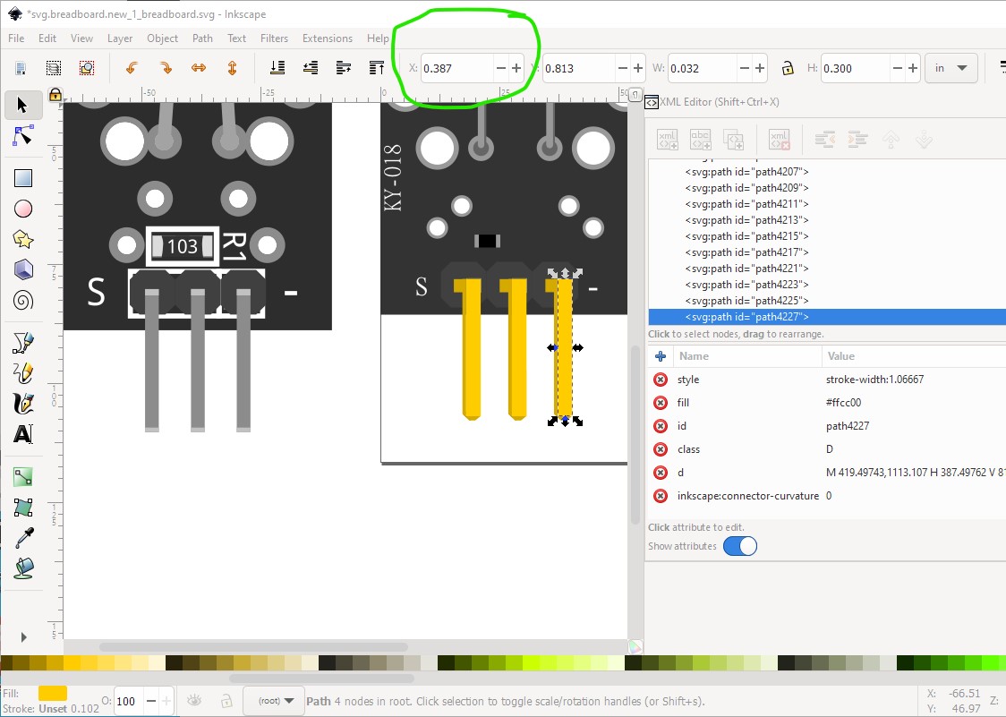
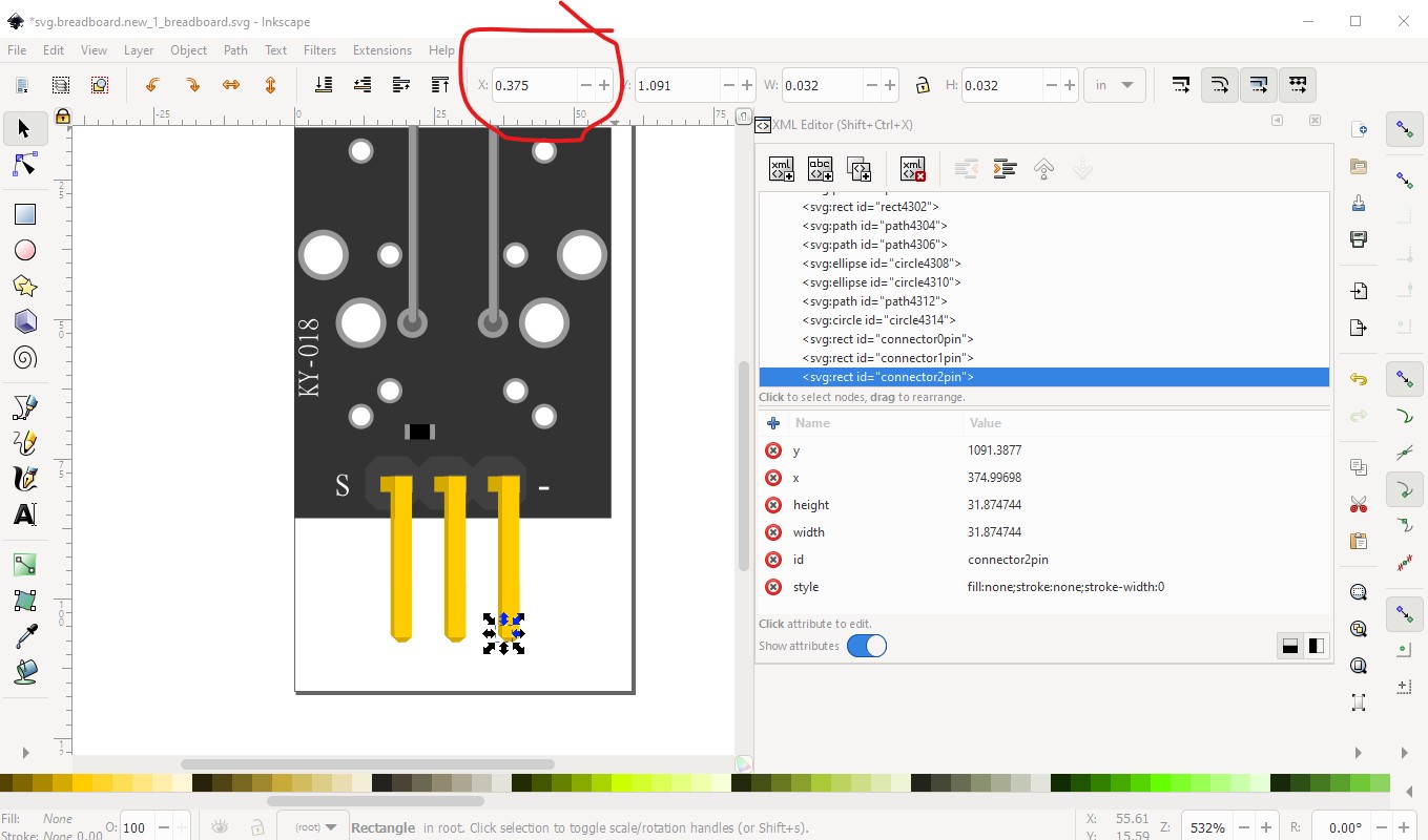
but connector1 and 2 are two large in x and need to be set back to 0.1in
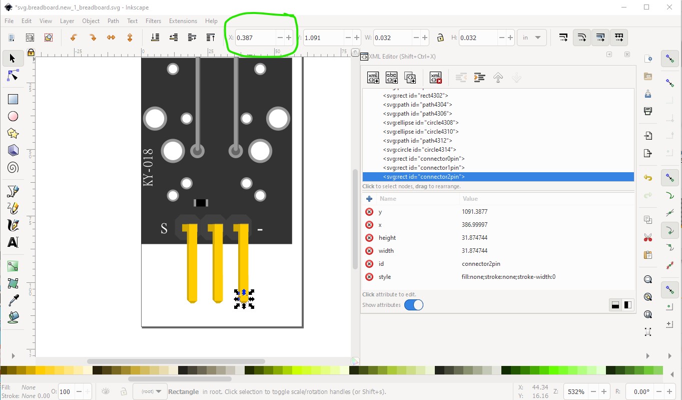
like this:
Now we need to fix the font family

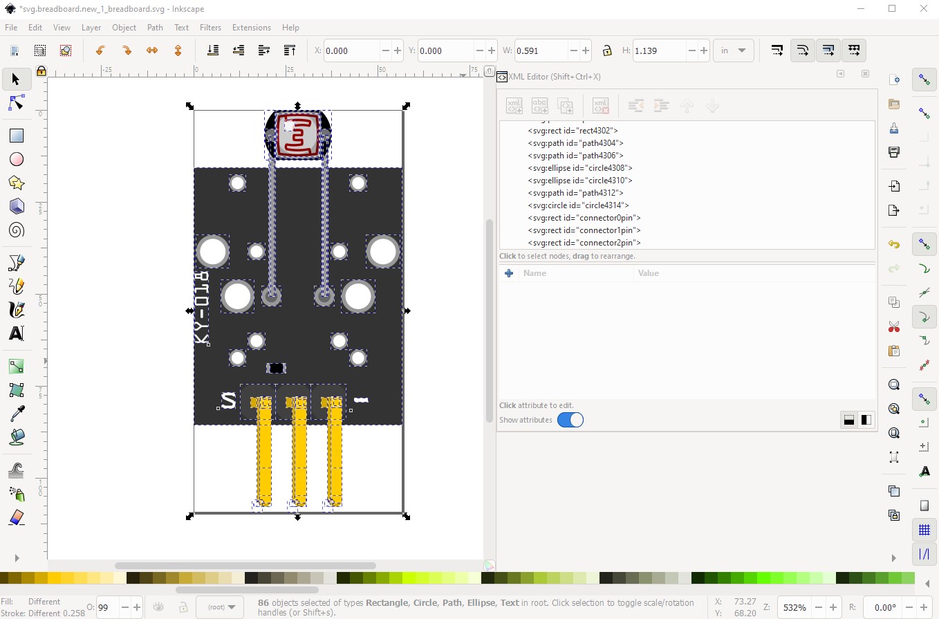
and do that for all the rest of the text as well. That should finish the corrections, so now we need to resize and save the image. So Edit->select all, because the viewbox is too large because of the rescale:

then Edit->resize page to selection to reset the viewbox:
then (with Edit-Select all still active) Object->group to set the layerId and change the id to breadboard
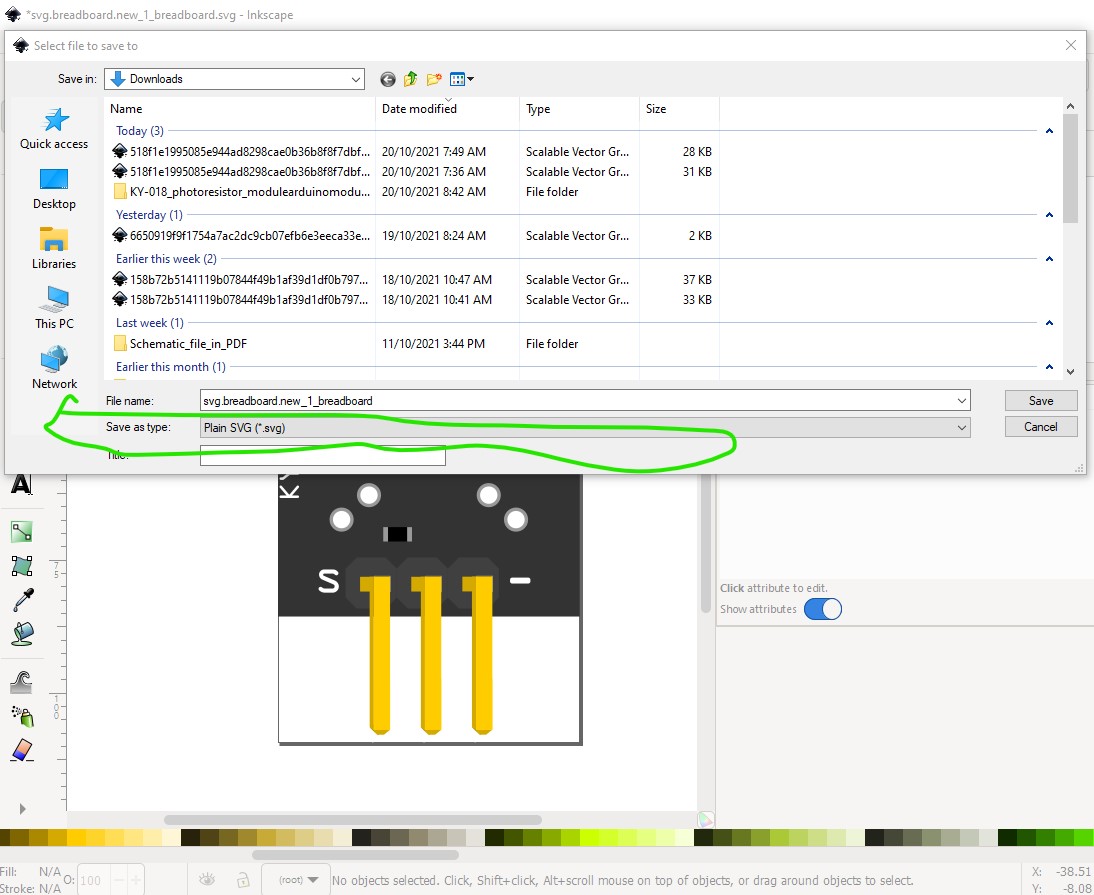
now File->save as and change the type to plain svg (which removes all the Inkscape specific metadata which Fritzing sometimes dislikes) to save the new image.
and now I can load the image in to Fritzing successfully:
although because I didn’t run the svg through FritzingCheckPart to remove the px from the font sizes the text is too large, so correct that by running the svg through FritzingCheckPart.py
owner@owner-PC /cygdrive/c/users/owner/Downloads
$ FritzingCheckPartw.py svg.breadboard.new_1_breadboard.svg
**** Starting to process file Startup, no file yet
**** Starting to process file Startup, no file yet
**** Starting to process file svg.breadboard.new_1_breadboard.svg
Modified 4: File
‘svg.breadboard.new_1_breadboard.svg’
At line 31
ReferenceFile
‘fc-51_85d98481ce3be6f2e9b641181c0f798b_1_breadboard.svg’
doesn’t match input file
‘new_1_breadboard.svg’
Corrected
Modified 1: File
‘svg.breadboard.new_1_breadboard.svg’
At line 54
Removed px from font-size leaving 48.9997
Modified 1: File
‘svg.breadboard.new_1_breadboard.svg’
At line 337
Removed px from font-size leaving 79.9995
Modified 1: File
‘svg.breadboard.new_1_breadboard.svg’
At line 350
Removed px from font-size leaving 79.9995
which corrects the problems
This is the corrected svg

Peter