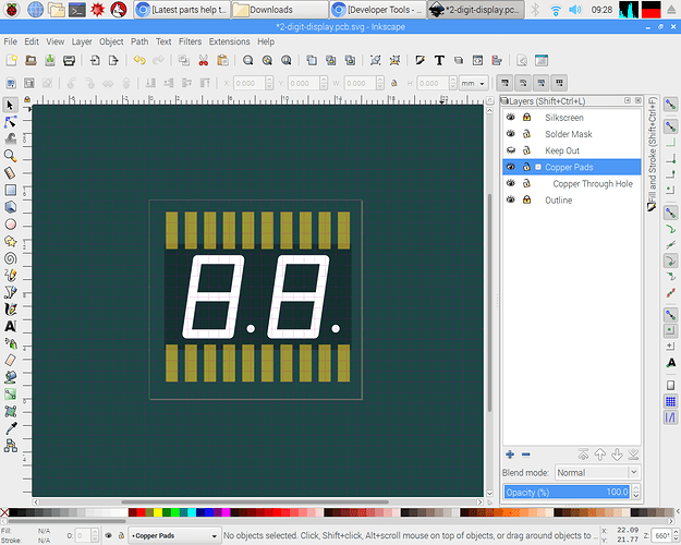
New Inkscape Templates

The TLDR is that I have created a new part kit. You can download it, and create new parts with Inkscape. Like the official examples, but better.

Fritzing New Part Kit on Github ~~~ Download Zip

When creating new parts, I was getting regularly confused about the copper layers, and all of the hidden features that the new parts guide doesn’t seem to cover.

What these templates can do for you

  1. Visualize all the groups in the layers panel
  2. Grids, & lots of them

What these templates cannot do

  1. Holes without copper

How it works

Hi there. My name is Wray, and I’m a web developer, SVG enthusiast, Inkscape expert, and Fritzing intermediate. So all I really did here was add all of the syntactic sugar that Inkscape uses to pull standard SVG elements into the user interface. That also includes meta information that allows helpful stuff like grid sizes and colors, snapping rules. There are 3 templates, one for each view, Breadboard, Schematic, and PCB. For the breadboard and schematic, the best thing is just having a grid that matches Fritzing’s. I also put the pins on an upper layer/group so that you can select the more easily in the part editor. The PCB template is obviously more complicated, and I’d like to add more features if possible. I’m especially still confused about if copper1 should be nested in copper0 anymore as it seems to have changed. Documentation is hard to find which is why I made these.

1 Like

Wray very very welcome aboard :slight_smile: . I’m Peter, Inkscape ignoramous, much better part maker. 3 years ago when I started I didn’t know what an svg was, nor had I ever used an svg editor. I still use about %1 of Inkscape usually in a very non standard manner (xml editor is my friend :slight_smile: ). I regularly have to reset the preferences.xml file after I do something (what I have no idea) that changes Inkscape’s behaviour in an odd and undesirable way (such as causing copies between svgs to occur as images rather than xml), so I hope you are up for lots of ignorant questions. There is a post about some of what we know about Inkscape here, feel free to add to / correct it:

That said I’ve downloaded your archive and had a quick look and see some changes that are desirable. You are correct the template files on the web site are a disaster. They are old, dimensioned in px from 72dpi Illustrator. They load correctly in Fritzing (because it will guess, sometimes incorrectly what dpi to use), but in modern Inkscape they are wrong. I have been working on a corrected set of templates, but been distracted by other tasks. Currently upgrading the parts checking script at

to only check the part (and do a better job of that) so it can be added to TravisCI on the parts repository tool chain to check parts submitted for inclusion in the repo, then to fix up the parts factory to emit parts with the correct scale and line values. I’ll work on modifying your current example svgs in to something that matches the part file format here:

and the graphics standards here:

http://fritzing.org/fritzings-graphic-standards/

and either post them here or make a pull request on github as you choose. Hopefully we can come up with something that could replace the current template files on the web site (possibly once the web site clean up is finished, I understand it is in bad shape currently as is most of Fritzing).

Peter

1 Like

Hi Microrwrave, thanks a lot! Hopefully after the 0.9.4 release I will have more time to care about the parts editor and the documentation. I’d suggest to add/link tour templates in the wiki.

Pretty much most of the advice in that other thread about ungrouping is not good advice if you’re not set up with properly ID’d and Layer’d groups like in my kit. Folks have misunderstood Inkscape for over a decade that groups and layers are the same thing—the fault of the Inkscape devs which we could use more of. But anyway, if you start with my kit and use any of the advice from that thread, apply transform might be the only thing i’d say is okay. But even ungrouping constantly, you won’t be able to break copper0 and copper1 anymore because i’ve set them as layers and ungroup will leave them intact.

While I’ll have to poke more, that may be a bad thing if that creates translates in copper1/0, as Fritzing’s gerber generator doesn’t deal with translates or inheritance pretty much at all as far as I can see, (as demonstrated by the thread on surface mount esp32 won’t pass drc (where translates in the pcb layout are breaking drc.) I for sure don’t understand Inkscape, but neither by and large does Fritzing. That is mostly Fritzing’s fault as the two are doing different things, but we need to find a way to convert from Inkscape’s way of doing things (such as CSS which Fritizng doesn’t support in places) to something that Fritzing will support (which may be more CSS support as development restarts).

Peter

OK, I’ve done some poking at your templates and have some questions. I started by making a real part to use the templates on, a simple 3 pin right angle header which meets the requirements of the graphics standard document in scale and colors etc. For the schematic svg I copied the schematic from a 3 pin male header, which as usual the forum refuses to upload, so do the also usual and add a .fzp to the end of the svg so the forum will upload it. Remove the trail .fzp from this and you will get the svg in question.

svg.schematic.3pin_ra_header_1_schematic-orig.svg.fzp (4.6 KB)

This svg is of interest because parts factory is currently emitting wrong scale svgs for headers (ICs are the correct 10.41667 scale) and thus needs to be rescaled to meet graphics standard document, and I have some Inkscape questions about this process that I hope you can answer. So load the above svg in to Inkscape. It looks like this:

We see the scale (in the doc properties window) is 0.75, not the desired 10.41667 which will make drawing units 1/1000 of an inch. So we need to rescale it. To do that ungroup the entire document, then do edit->select all and Document Properites->Resize page to content->Resize page to drawing or selection to resize the viewbox to the drawing. This should always be done as the last step in a part before regrouping, as if you don’t pin alignment to the .1 grid in Fritzing often goes wrong, also anything outside the viewbox will be truncated on display. The only exception to this rule is with bendable leg parts where the legId must be outside the view box (and will be truncated) for bendable legs to function correctly. After this step the svg looks like this:

From this record from the tool bar (set to px for maximum resolution) the x y w and h values in this case

x 0 y 0 w 19.637 h 26.017

as we will need these values after the rescale. Now with the edit->select all still active change the document properties scale value from 0.75 to 10.41667 then click in the canvass (the image viewing area) to make it take effect. That will produce this:

Now we are going to set the original values back in to the tool bar to rescale the drawing. So set 0 0 19.637 26.017 back in to the tool bar one value at a time. In the tool bar restore y to 0:

in the tool bar restore w to 19.637px

Note although I changed only width, the y coord has changed to 0.092 from 0 (which is why I am using this level of detail, because there is an Inkscape question coming at the end of this.) in the tool bar restore h to 26.017 whic produces this:

now y is -0.264 instead of zero, w is 18.685 instead of 19.637 and height is 26.373 instead of 26.017. Resetting the values (sometimes several times) will converge til the numbers are finally correct. I would much like to know how to set Inkscape to not modify values that I am not setting! After 3 passes of resetting y, w and h to the desired values convergence is achieved:

I suspect this has to do with scaling stroke widths, and converging is the only answer, but I would like to be wrong! Now Edit->select all, Doc properties resize page, group, change group id to schematic to set the layerId and File->save as type plain svg to produce:

svg.schematic.3pin_ra_header_1_schematic-rescaled.svg.fzp (4.6 KB)

Run the new part through FritzingCheckPart.py to check its format. Then using 7zip, zip the 5 files (the fzp and 4 svgs) to make this part:

3pin-ra-header-orig.fzpz (7.6 KB)

Load it in to Fritzing and test it. Now copy the example.breadboard.svg file from the parts kit in to svg.breadboard.3pin_ra_header_2_breadboard.svg with the intent of making an identical part using the templates from the kit. Edit the svg in Inkscape which indicates the scale is wrong (25.4 instead of 10.41667):

record the tool bar coords (after changing to px):

x 0 y 0 w 57.600 h 39.400 which produces:

but changes the grids offsets (which I guess is due to the rescale):

so change the grid back to what it was. Then saving as plain svg (whch is what Friting likes best) appears to delete all the layer information as well as changing the scale to something other than 10.41667 even though that scale was showing in Inkscape.

from this svg file

svg.breadboard.3pin_ra_header_2_breadboard.svg.fzp (1.5 KB)

One other thing that I would find useful is how to increase the contrast on the grid lines. As we see in this snip while the major lines are fairly visible, the minor lines (set at .01 of an inch with major lines at 10 which I find most useful) is almost invisible. Is there a way to increase the contrast of the minor grid lines?

grid-contrast

Peter

I use a XP-Pen Deco Pro Android Drawing Tablet and the pencil tool for drawing in Inkscape . it works beautifully most of the time. Sometimes the calligraphy tool doesn’t seem to pickup pressure even if it is set to. I can see the pressure works in the tools dialog, but it has no effect.

Overall it is great though. For some projects, if you use detailed sketches for instance, it is probably better to use the bezier tool, but you can sketch with the calligraphy tool quite nicely too.

While that looks cool, I fear I don’t have anywhere enough skill to use it effectively :slight_smile: . I can barely muddle through Inkscape far enough to make parts (as will become evident when I finish the part making tutorial and demonstrate exactly how little of Inkscape is needed to make parts.

Peter

Wow! you did a good job! looks awesome, do you use a mouse or a pen tablet for Inkscape? which one is better?

Personally I use a track ball.

Whichever is easier for you to use. The complexity is figuring out Inkscape and the incompatibilities between Inkscape and Fritzing. These two tutorials cover current versions of Fritzing (many of the others are for older versions.)

I lately learned there aren’t links to the videos in Old_Grey’s tutorial so you need to do a google search for the title and then they come up on YouTube.

Peter

I also use a trackball to answer the question.

But also wow! I haven’t looked at this in years. Quite surprised I was able to recover my forum account too because microwrave isn’t a name I use anymore.

I’ll put a reminder on my list to answer more questions above. I’m betting that Inkscape 3.0 makes some of these things not work anymore.