i see , so i have to sort of drill a hole in it?
No the board maker will do that. You (or more likely me) just has to drag a hole part in to the sketch to get the hole drilled.
Peter
yooo thats wicked
i got scared that my clumsy hands would have to drill a hole lol
Do a search in the forum like this select search (the magnifying glass), enter the fzpz file name in the search bar then click the green circled icon on the right

and this screen comes up
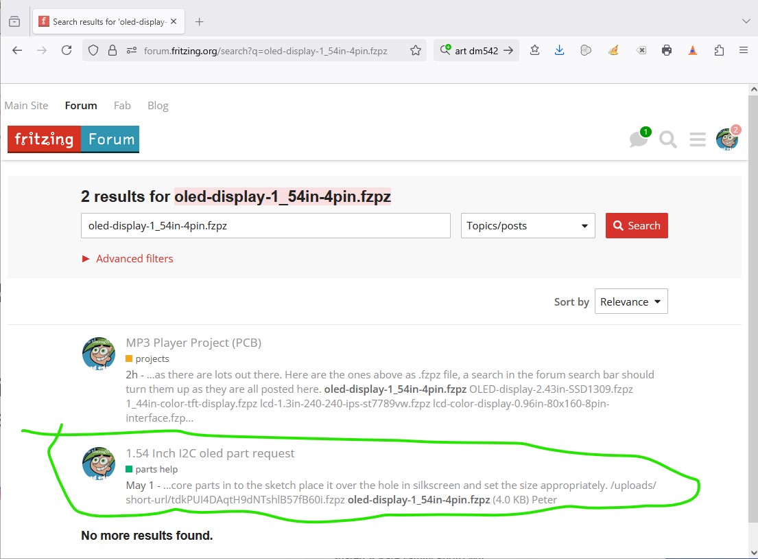
the first post is this one where I listed them all, the second is the post where the part is ready for download.
Peter
okayy lemme view the screen
i think the 1.54 inch oled is the one best suited for this ! i think thats all we need !
thank you so much!
What about the 3.5mm jack? Do you want to go with a solder terminal one that connects via wires (either via solder in which is more mechanically stable or a male/female header or connector.) This is what I would do because it will be a pain fitting the pcb in to a case if you have to get the jack through a hole in the case.
Peter
the solder tab would be our best bet , itll be space saving and we can replace it easily if its damaged
The board just got a bit bigger because the new display is larger, and I think there is a problem with the encoders. They are a breakout board and I just realized they mount at 90 degrees which may not be what you want. From the breadboard view of the encoder

It is intended to connect via the right angle header which isn’t what you want here. You want the bare encoder to solder on to the board I expect. There is an alternative part here, but I don’t know if it will do what you want (I think it is mechanical rather than optical as the RSdelivery one apparently is.) The RSdelivery one could have the right angle header unsoldered and the part modified to mount it flat with the shaft going vertical (which is I think what you want.) A better bet may be unsoldering the encoder part and making a part for that (but then we would need to figure out the pin spacing which shouldn’t be that hard with calipers. There is one that I think is similar (but perhaps not identical) that has a Fritzing part here:
Unfortunately that post doesn’t give the Alps part number for the encoder I think it is probably this one.
I also don’t know what the AZdelivery one does exactly other than it has a NO pushbutton switch as this one does. Neither of them say how many pulses per revolution. If you already have the AZdelivery ones you could unsolder the encoder from the board and I can (given the pin spacing make a part for it which may be the easiest solution. Here is the new board with the 1.54in OLED installed and pcb enlarged a bit, the alps encoders installed (but not in schematic yet) and placed where I think is sensible. You can move them around to suit your needs as long as you watch the overlaps. The MP3 player moved to the edge of the board because you will need a slot in the case to insert the SD card in to so you need to take that in to account too. Here is the sketch
MP3_ESP32_ONLYSCHEM-improved-18650.fzz (114.2 KB)
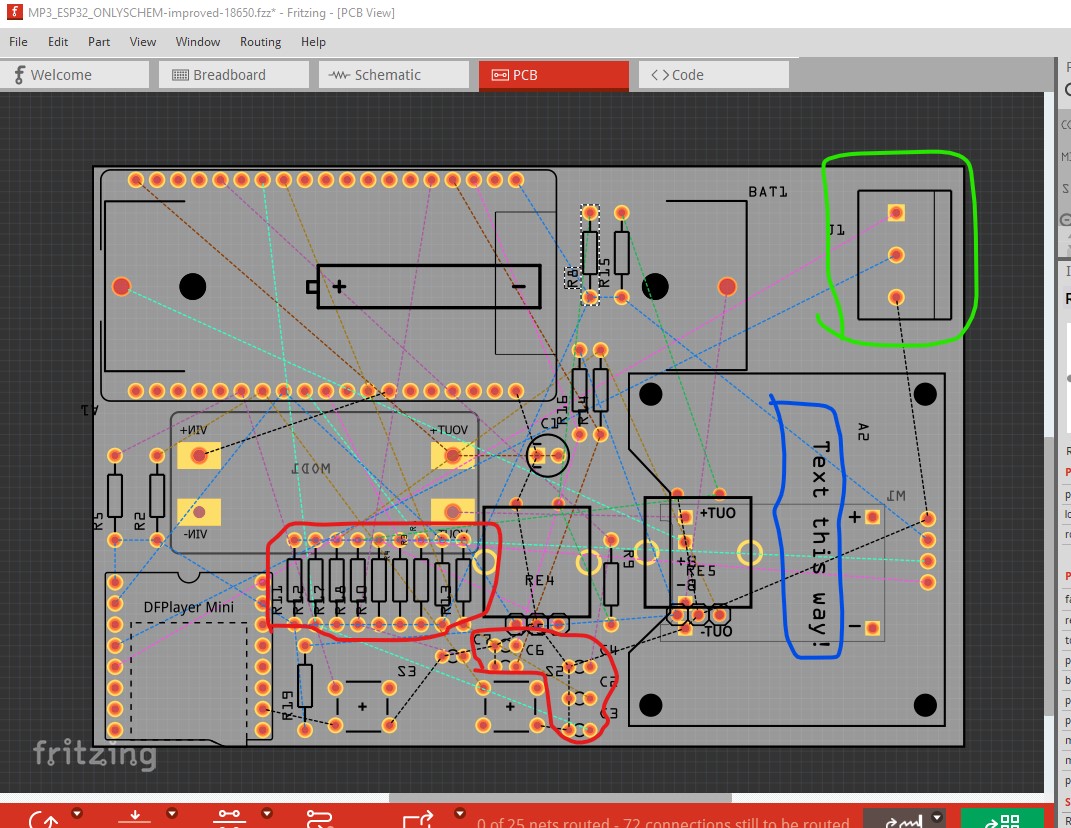
and an image of what pcb looks like.
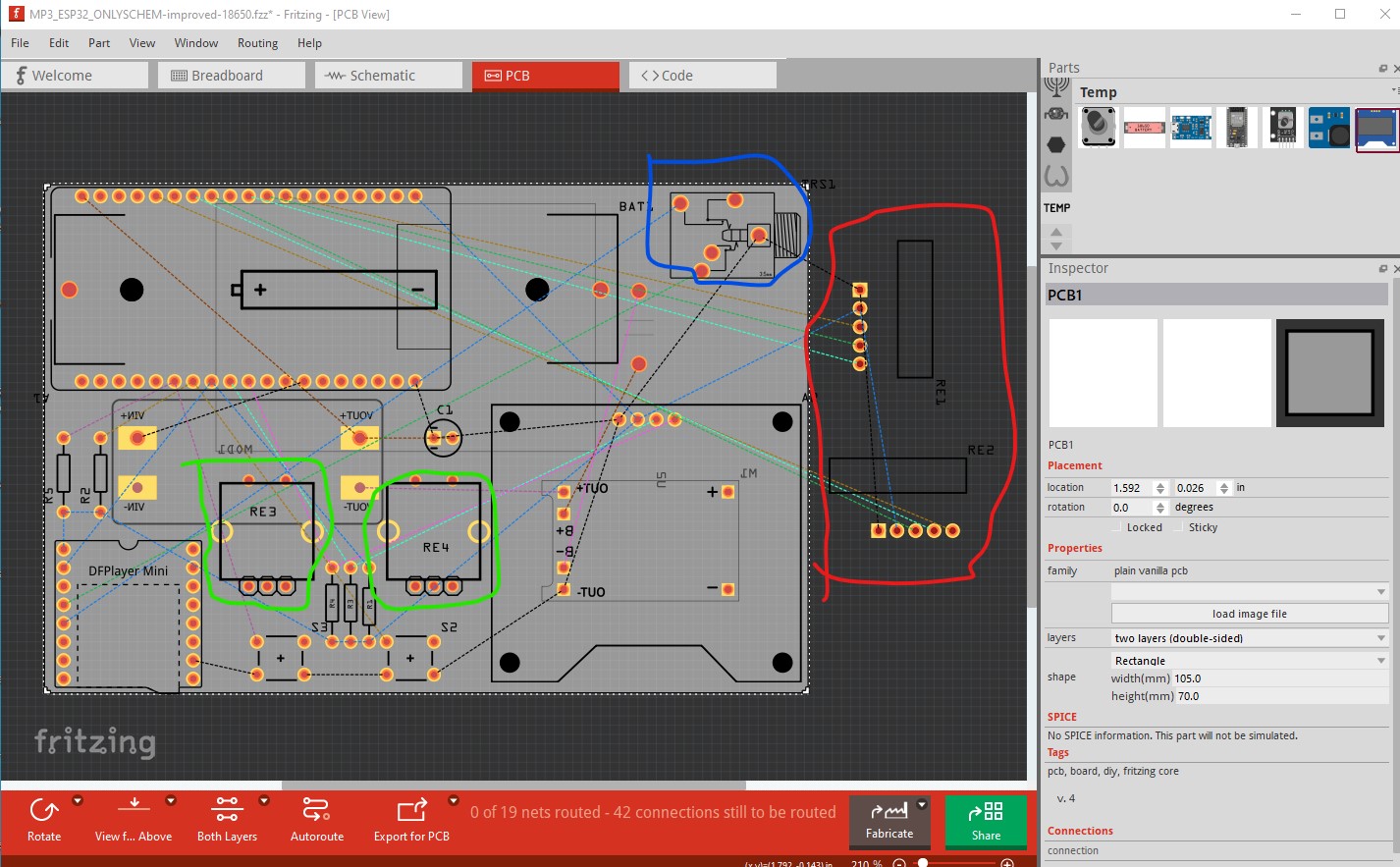
Note the size of the pcb (in the lower right Inspector window) has increased a bit to allow for the size of the new display. The new encoders are circled in green, the jack circled in blue is only for the wires to the real jack on the case, the old encoders are off board and circled in red. As noted you can move things around as you like to get the layout you need as long as parts don’t overlay.
Peter
So you’re talking about using a bare EC11 rotary encoder right ? We can use that , I think there might be parts in fritzing for that or may be in the fritzing forum .
And for the 3.5mm jack , could we use screw terminals so that we can connect the solder tab easily ?
And can you please show the charging module once ? I don’t have my laptop today and I can’t view it on phone
Also I think that the oled would be better if it’s rotated 90° clockwise
since were using the 18650 now
the lipo battery we should remove right?
@vanepp also can you send a pinout of the Alps Encoder? i cant find a proper pinout.
Also I was thinking , would using a ribbon connector display save some space ? Eg a 1.54inch IPS TFT with a FPC ribbon
OK a new layout with your changes added and some more questions ![]() : . First the encoders. Yes there is one in core parts, but it doesn’t have the switch that is in the KY-40 encoder the unit circled in green is the one from core parts note it doesn’t have the two pins on the top that the one on the left does for the switch. Since you have the switch connected to the ESP32 I assume you are using it for something, if not the unit in core parts will work fine. The one on the left is a part I made for someone a few years ago that adds the switch.
: . First the encoders. Yes there is one in core parts, but it doesn’t have the switch that is in the KY-40 encoder the unit circled in green is the one from core parts note it doesn’t have the two pins on the top that the one on the left does for the switch. Since you have the switch connected to the ESP32 I assume you are using it for something, if not the unit in core parts will work fine. The one on the left is a part I made for someone a few years ago that adds the switch.
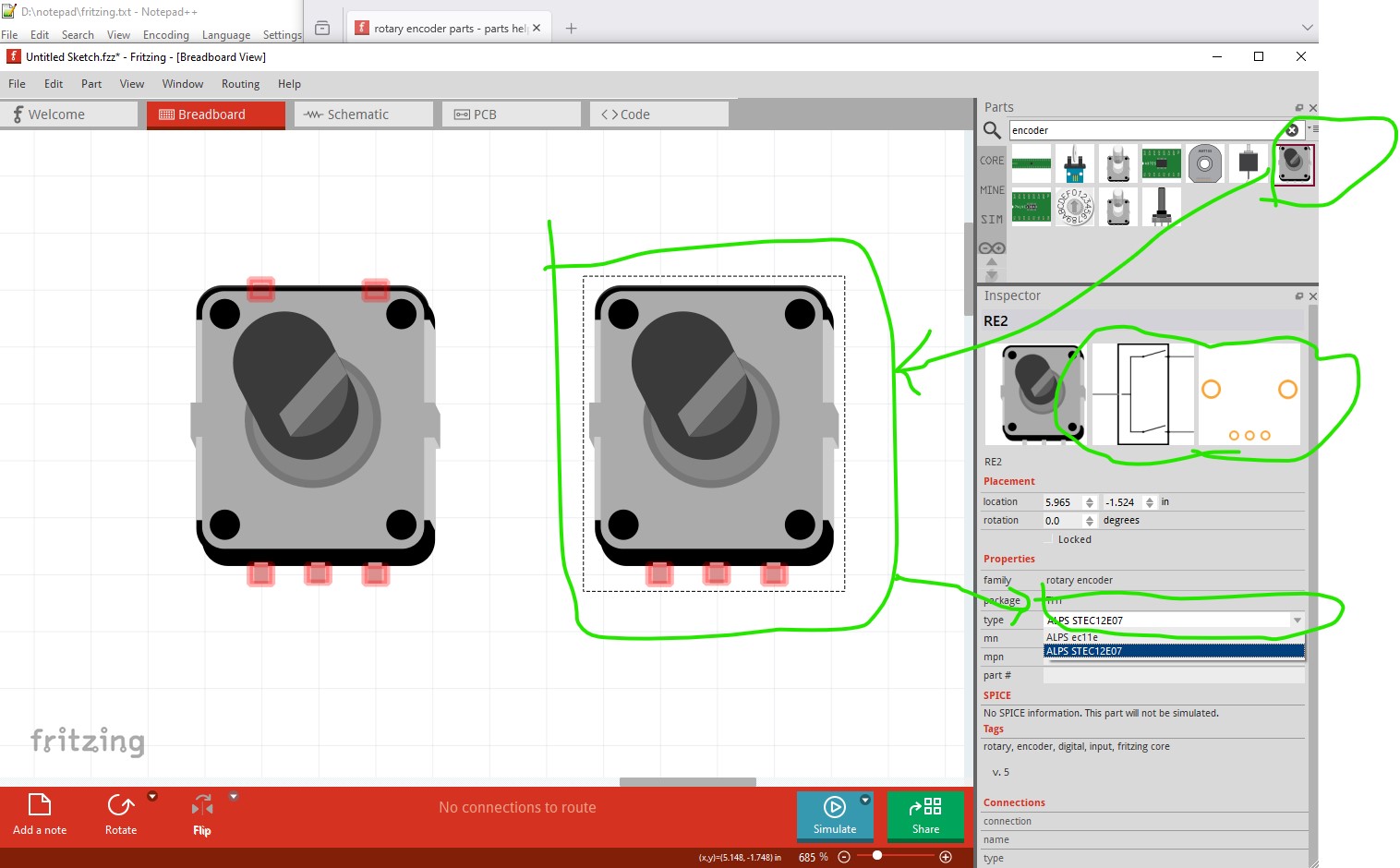
this is the encoder on the left. It has a push button which is activated when you push the shaft down as noted. Because it is connected I assumed you were using it, If not we can use the part from core parts.

I looked for the encoder used in the KY-40 boards, and it seems they are incorrect, the encoder is not optical it is mechanical. This article is the most illuminating that I found
so I found a Bourns encoder data sheet with a suggested bounce filter, but it is fairly complex
The schematic with this implemented looks like this

I note that the article above uses a only the capacitor (which needs to be near the encoder as he notes) without the series resistor which may be a reasonable compromise because this adds a lot of complexity in pcb like this
This sketch has the debounce hardware in it (although pcb wasn’t reconfigured yet)
MP3_ESP32_ONLYSCHEM-improved-18650-hardware-debounce.fzz (115.2 KB)
and crowds things up. The alternative is to debounce the switches in software (which is likely a good idea anyway!) and just use the pull up resistors. The idea of using a screw terminal for the output jack is a good one (and has been done in both sketches.) The screw terminal provides a secure (by the screws) mechanical connection to the external jack which is mechanically a much better idea. I rotated the LCD display 90 degrees clockwise, but realized that rotates the text 90 degrees clockwise too, so I rearranged most of the boards (taking in to account which ones need slots in the external case for access ports, there are a few!)
MP3_ESP32_ONLYSCHEM-improved-18650-no-hardware-debounce.fzz (110.0 KB)
which looks like this (with the debounce hardware removed)

and like this in pcb with the components moved around

The purple circles indicate holes in the case (for the two USB connectors and the CF card.) It may be better to rotate the ESP board 90 degrees so all three holes in the case are on on side of the case to make hole positioning and pcb insertion easier during assembly. As well if you are intending on using wireless on the ESP32 the antenna (circled in red) may need to be clear of the battery. The metal in the battery will likely affect wireless connectivity (and discovering that after ordering the board is painful!) as noted above rotating it so its USB connector is on the bottom may make assembly easier as well and may be worth doing. The battery controller between the MP3 player and the encoder has a usb port to charge the battery. It also has pads on the board that can connect to a 5V source on an external connector to charge. I assumed you would be charging via the USB connector, but the other is possible as well. As noted above changing the rotation of the display changes how the text is oriented, as a result of that I moved the encoder and the switches to (maybe) better match the new layout. You can move them around (with the usual warning about paying attention to part overlaps!) if you like another arrangement better. Another consideration is the push button switches Their push buttons may need to be the taller type like the one on the right here.

to be accessible from the case as the switch will be flush to the pcb which will be fairly far down due to the size of the display and the ESP board. You should consider whether there are other mechanical issues you need to resolve too, it is much cheaper to make changes before you have produced boards than after ![]() .
.
edit:
A late thought. It may be sensible to mount the display on the case, not solder it to the board. The other components may make getting the display properly aligned with the hole in the case difficult. Wires soldered in to the display and to the board would connect the two without connectors to fall off.
Peter
1 Like
Waitt lemme get on my pc
as for the debounce, i can easily handle that in software using pullup resistors cutting cost as well as clutter , and if the antenna is getting sort of blocked, rotating it would be good but the battery is so big that despite rotating it on the same side as the df player and charger, the antenna was still blocked , and yeah , the taller switches are wayy better and i have to admit that i totally forgot about the height of the buttons ![]()
![]()
tbh i think using a oled display with fpc ribbons would be our best option , its neater and gives us more space , however i cant really find a screen which matches the criteria , i found a screen from eastrising but i cant load the image, cant find a fritzing file as well
and the ZIF connector
Easy enough to make parts for both. There are 20 and 40 pin fpc connectors available but not at present a 24. I will make both. Hand soldering the fpc is likely to be exciting if you don’t have an SMD oven though.
Peter
i hope soldering the fpc isnt too hard, if i mess up too much my dads friend has a convection oven so ll use that hehe , also ill have to surrender my laptop in a while and wont be able to view fritzing files on phone but ill still be awake for 1 more hour though i guess
It will likely take me longer than that to make the parts so you will probably see them tomorrow, but they should be up by then.
Peter
1 Like
Oh I see , best of luck making the parts and thank you again for your hard work ![]()
![]()
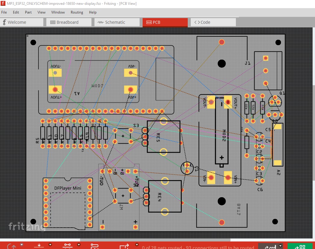
OK, about time for me to head off, but there is a part for the new display and its connector (although the connector is included as pcb view in the display part so you don’t need both.) There are still some issues to be resolved with the new display so in this sketch it is present but not wired to anything yet. The board has gotten bigger yet again, to move the battery further away from the wireless antenna. There is a second boost converter added because the new display requires 12V as well as 3.3V and wants power sequencing (which will probably require a mosfet capable of being switched at 3.3V which isn’t present yet.) That will be tomorrow sometime. The two items circled in blue are the new additions (the second boost supply and the display. I also added mounting holes on the 4 corners as you will probably want to use them to fasten it to the case. You may want to center the push buttons and the encoders to make the case look neater. Note the fpc connector is 0.5mm pitch so it is very dense and likely to be hard to hand solder. Your best bet would be to buy the connector that the display vendor offers because that is what I used to in the display part. Here is a copy of the new sketch so you can move things around to a layout you like. Tomorrow I’ll look at what the power sequencing needs. It wants VCC (I assume 3.3V) present for some time before 12V is enabled (thus the mosfet to make that switchable.) It may also want a progammed shutdown I don’t know yet.
An image of pcb as it is presently configured and the new sketch that the image came from.

Edit:
OK, the morning update (and a new sketch.) I think I have the new display connected in schematic and the parts more or less arranged in pcb. I used this post to figure out the necessary configuration.
I assumed I2C interface and selected SA0 as ground (as it doesn’t say what the address is if the pin is high!) The 12V to the display is switched via a mosfet controlled by a pin on the micro so the necessary delay after VCC is high can be achieved. You will need to prototype this to make sure it works as designed although I think it will. The display needs to shut down 12V before VCC goes down so you will need to provide a shutdown procedure that produces that effect (by turning off the mosfet for a while.)
MP3_ESP32_ONLYSCHEM-improved-18650-new-display.fzz (154.2 KB)
as before at this point you can move things around if the layout doesn’t suit. One thing I can think of is you may want to center the switches and encoders to make the case not look lopsided. You may also need to move the display connector because I expect the fpc cable will need to connect at right angles to the connector in order to connect. Layout looks like this
While I used a second identical boost supply, that may well be overkill. The display only needs micro amps at 12V so a simple switching boost IC would likely do the job (or a 3.3V to12V module of some kind.)
Peter