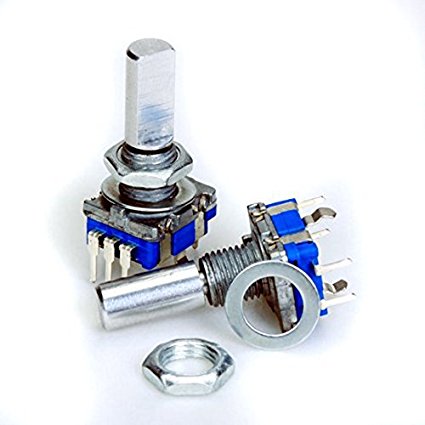
hi all, I would need to use this type of rotary encoder for my project but I can not find this part anywhere online. Can someone help me? Thanks in advance
I can’t see the pins but I assume it’s not in FZ part search, and I hope you did a Google search for the part because that takes us a lot of time.
You will have to provide a link to the datasheet or a pic with the actual dimensions of the footprint it requires.
As @Old_Grey said, a part number or data sheet is the starting point after you have typed rotary encoder in to the part search (the magnifying glass in the parts bin on the right). Around 6 different rotary encoders come up for me. If one of those won’t do we would need a data sheet to help.
Peter
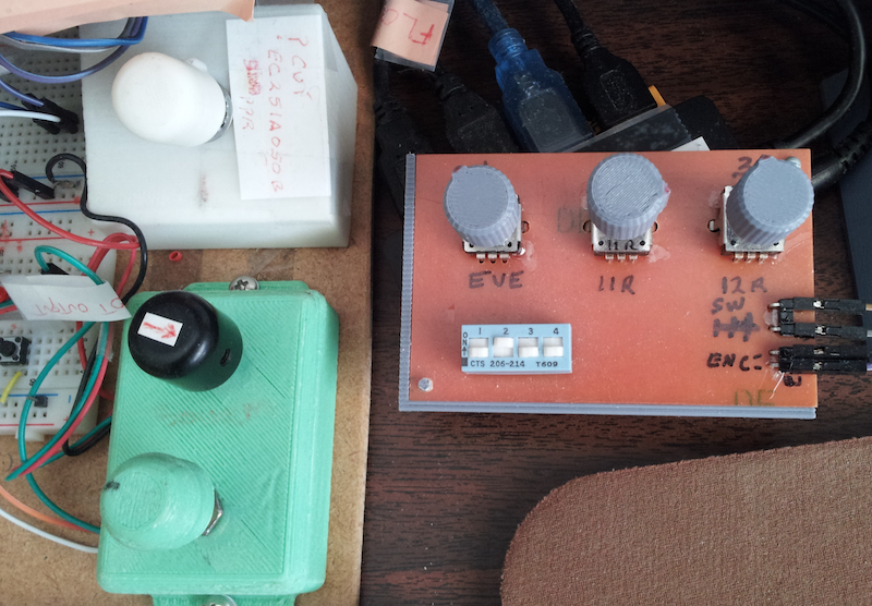
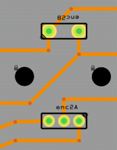
I use quite a few different encoders - enough that I made several encoder test gizmos.
As pointed out, the Spec Sheet is the starting point.
Several of the same Physical-looking parts do have different pin attachments for GND and A & B.
Take note that even the same brand, same looking… but, pins are different…
Regarding the Fritzing part:
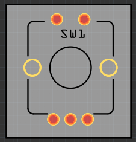
Usually I use the Pin part with 2 & 3 pins and the Hole part for the 2 retaining legs.
However, there is a Fritzing Encoder Part that works - it has 3 pins and 5 pins and 2 retaining legs. I don’t hook up the the un-needed pins (the extra 3 pins on the 2pin side).
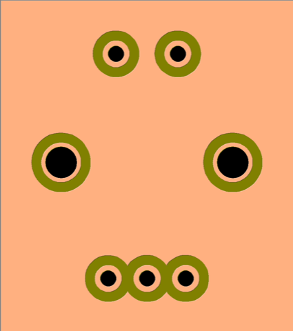
Images of test encoders and the Fritzing encoder
hello guys,
thanks for your clarifications. Unfortunately, none of the components in the library match the correct one for my needs. the distance between the holes and also the fixing legs are different. I found the component datasheet but I am not able to create a component. Thank you for your availability.
I think (note the weasel word  ) this will do what you want. It is basically the alps encoder from core with the switch added (and a variety of other things such as rescaling, breadboard, schematic and pcb modified to add the switch). I assumed the original pads were the correct size for the alps parts because the layout was similar (if missing the switch terminals). Before ordering boards with this pcb footprint, print out a copy and check alignment and hole size against the real part (I don’t have one to do that with). Note the called for square holes for the mounting pins are round holes in this case as Fritzing (AFAIK) doesn’t do square holes.
Rotary Encoder ec11e.fzpz (9.7 KB)
Peter
1 Like
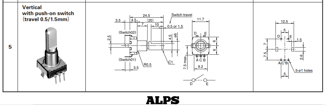
This should help…
First, recognize that dimensionally, decimal places of 0.1, 0.2… up to about 0.5 mean very little when placing components on a pcb as the pins are flexible enough and the holes are large enough.
Second, the outer dimensions of 11.0 to 12.5 are fairly irrelevant unless you’re trying to squeeze a square peg into a round hole, so to speak.
Meaning, ‘ballpark’ dimensions have been good enough for me and stuff I have flying in outer space for the past 40 yrs…
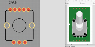
Having said that, attached is what I use for all of my 12mm (approx dim) encoders (ALPS, BOURNS, PANASONIC… many others). Some of the actual encoders are 11mm, some 13mm… But, the pin spacing is what is important and the ones I use are all within about 0.5mm of each other.
Attached is a file of what I use as a baseline and will work for you. Sure, you can move the pins&holes if you must but, there’s no need… The screenshot is from actual part in a circuit on my desk…
enc_Baseline.fzz (1.5 KB)
Thanks! I’ll compare this with my current footprint and see if I need to make changes. Having a footprint that someone has used is a big help!
Peter
Thought I’d challenge myself and try making a Part.
It’s not as easy/simple as it should be but, I think I have some success…
Attached file is for the baseline geometry that should work with/for a typical 12mm (+/- 1 or 2 mm) with typical pin spacing.
I used the ALPs RGB led Encoder as a starting point.
I did not spend much time dolling it up/tweaking and customizing the metafile…
But, I did export it for production use and brought it into CopperCam (I use it for CNC milling PCB’s). Seems to be okay!
Encoder.fzpz (10.7 KB)
Your part has a number of issues, the most serious being hole sizes. The part has these (in the gerber):
INCH
T100C0.082677
T101C0.043307
The first being the two mounting holes and the second being the
5 pin holes. Neither seem to be standard drill sizes, the first will probably round up to .0860 and the second to .0520 (being slightly larger than the standard .042 used on the 1n4001 diode for instance). They are also quite different from those in the enc_Baseline.fzz file which are:
M48
INCH
T1C0.125000
T100C0.039370
T101C0.038000
Which are 1/4 inch for the mounting holes and .038 ( the standard hole size for .1 square posts) for three of the pin holes and .039 (which I expect should be .038 like the first three) for the two switch positions. As well since schematic (and possibly breadboard too, I didn’t check it) has pins assigned incorrectly you are getting the red square indicating pins not assigned in pcb view in Fritzing. If you can confirm which set of hole sizes is correct I can substitute your pcb view (from either the fzz file or the fzpz file) in to pcb view on my part to get one with a tested footprint.
Peter
You probably need to watch my tutorials to make more efficient parts, because there is a lot I would change in PCB view, but you’re getting there.
Thanks for taking a look at the part…
I totally agree with all that was said. I too saw the problems when I looked at the file again. It was weird and, there’s some big red rectangle in the middle - where that came from is beyond me!
But, it was a start at hacking a part and a good lesson to confirm my opinion (re: the pain of making a part) and that my previous posted example of using pins and holes works best for me.
The red box is because you didn’t allocate the pins in FZ Edit. Did you see and error of pins not assigned.
There was no instructions and no one to help on the forum when I started 2.5 years ago, so when I knew enough I made the video tutorial series. The problem is that people think it’s too long and don’t watch it - I shouldn’t have wasted my time -, but the 2 hours spend watching them - you can speed them up in the YT settings - will save you ten times that in fumbling around.
I admit to quickly throwing it together but, I did read through a few instructions and felt I had enough of a handle on it to make a start.
When doing it, I had no problems and saw no errors. In fact, aside from the hole diameters, it worked well in CommperCam (CC) - no big red box… nothing to indicate errors and I wasn’t concerned about the hole diam’s as I always set them to my preferred dim in CC.
Here’s a screenshot of it in CC.
When I saw the post citing the problems, I opened the file and was surprised to see the problems.
Perhaps I’ll try it again but only to feel I’m not too old to learn… But, for practical use, grabbing (as a group of items) the pins/holes from a file of parts I regularly use is fast and mindless…
1 Like
It actually isn’t in your pcb svg, but rather schematic where the pins don’t match. In Fritzing all three views breadboard, schematic and pcb are linked together and a change in one reflects in to the other two (and errors such as an undefined pin in one view also reflects in to the other 2).
I’m a fan of doing what works best/easiest for you ![]() . I’ll adjust my part to match the hole sizes and positioning in the fzz file and post that part. Then you can, if you wish, use a part instead of your current method or use your current method if that works better for you.
. I’ll adjust my part to match the hole sizes and positioning in the fzz file and post that part. Then you can, if you wish, use a part instead of your current method or use your current method if that works better for you.
Peter
Thank you! That would be great and (then) others can use it.
I took another stab at it this morning (following some guidelines). But, the Red thing shows up and your comments clarify why…
I intend to use the part you create (or my cheating approach) but, for my education, it would also be good to succeed with a part from scratch as I have several parts I could create.
I read that, and this is a quote from some info, “you must begin with a part that already exists”. That’s what I did with the part I posted (used existing encoder)…
While using existing part may be the case, for me, if I can’t do something from scratch, well, it’s not something I find user useful…
I can understand others wanting/needing a complete part with necessary items for Schematic, BreadBoard, PCB. But, I don’t, thus, I didn’t bother with items other than PCB (it seems I should be able to delete/avoid stuff I don’t want)… All this goes to further highlight the common knowledge of shortcomings for Part making.
I will say this in regards to Fritzing - despite it’s shortcomings, it’s a great app and I stopped using others (Eagle, Kicad… several others) and have made something on the order 100 PCB’s using Fritzing (most via CNC but several via thermal and chemical transfer).
The thing that most annoys me is it’s constant resizing of the Display Window. I don’t want to toot my horn but, aside from engineering, I’m a successful programmer and window sizing is, basically, a no-brain aspect of creating a window and should be user tweak-able… Meaning, once sized, it should retain the size and location…
Thanks again and I look forward to your part: 
I spent too much time trying to get a tweak to work - I did the part just as indicated in the confusing documentation but… nope.
In the end, until your part is available, I did a cheaters approach:
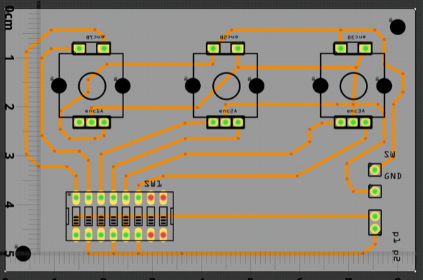
I used my pins/holes method and overlaid a SilkImage. While dim’s are not exact (who cares), it does convey the part outline. Attached is the file for a simple Encoder Tester having three encoders with the SilkImage’s…
Encoder_Test_Board1.fzz (22.8 KB)
This part should do what you want. You should still print out the footprint and check it against you actual part, but the footprint should be the one that @opera_night has had success using (although if @opera_night could check the gerber output from this part to make sure I didn’t screw up that would be great!)
Rotary Encoder_new_footprint.fzpz (9.3 KB)
That is what it says, and by and large it is correct (although incomplete). It is possible to make a part from scratch, it is just usually hard and inefficient. A new part has a moduleId which is a hex string (prefix0000_5d6cd844d826943902922aee8f7f7dbe_1 in the case of the current part). You can make one of these yourself, but there are things (such as I think Fritzing version number) buried in it that the code uses to decide what version it should treat the part as sometime, and it must be globally unique in your version of Fritzing (and everyone elses if they want to use your part). I find it better to let parts editor do its thing to create a moduleId it will be happy with with the correct number of pins that I need (so it generates the xml boilerplate, I can do it but it is easier to just have to edit it) and then unzip the resulting fzpz file and edit the underlying files (the fzp file is some boilerplate xml that the parts editor can most easily create although the format is available in the parts fomat document here:
followed by the connector definitions, optionally schematic subpart definitions and optionally bus definitions. Once you know the format of all those it is possible to edit the fzp file and the svg files outside of the parts editor to successfully make a part. To help that along I wrote a python script (available on github) that given the fzp file as input will parse it to check the format is correct (and warn about things I know can go wrong but not break the resulting part and error on things that I know will break the part). There are still things about the fzp file that the code uses that I don’t know about, but I do know some of the secrets (breadboards for instance have a variety of differences from a normal part in the fzp file). As well that script (which has been run against this part to clean it up) also fixes a variety of things that Inkscape does of css compliance that fritzing doesn’t support.
I think this is a QT (Qt being the graphics framework that Fritzing is running on) issue rather than Fritzing (although it could also be a Fritzing issue). I have a develpment environment for the source up and have upgraded from Qt 5.6 that current Fritzing used to the current Qt 5.10 but havn’t run it enough yet to see if there are any fixes that help us on the Qt side. As you may have seen one of the original developers is also trying to redo fritzing as a web app in javascript (which is pretty much the only development activity that I’m aware of).
Peter
Thank you for the great info.
I dug up a document titled “Parts Bible” that goes through the items in the xml and I now understand the tasks at hand.
Perhaps the only thing that wasn’t clear is regarding the ‘moduleID’ and where it comes from. The explanation above helps and may look into the Python script.
I have QT5.11 loaded - use it for “C” and Android programming. Not sure if I want to bother compiling Fritzing but, it’s food for thought.
The Part you made is good - I compared it to mine and loaded the gerber into CopperCam (scrnshot attached). Thank you!!
So, I’ll spend some time making a part from scratch and will, no doubt, be back with a need for more help… FYI - though I 99% of the time I change the pads to Oval shape (in CC) because I like big pads and CNC machining can eat too much copper away from the pad (depending on several things), I wil, hopefully be able to accomplish oval pads on the parts I create but, that’s the least of my challenges in making a part.
[UPDATE] I think your schematic isn’t correct for most encoders - The center pin should be common with the switch pin. Pins A & B are the encoder signal pins.
Thanks again for the valuable help and sticking with me on this 

Do you have a url for that or is that the part format document on github? I haven’t seen a document with that title and I’d be interested.
Note I’m not sure of the entire detail of what is in the moduleId, but from reading the source it sometimes decides based on a prefix in the moduleId that this is an old style part. I’m not entirely sure how parts editor creates one, I expect a date is likely there somewhere to provide uniqueness but haven’t verified that.
Getting someone familiar with Qt working on the code would be wonderful. I’m not particularly a developer nor a c++ programmer so I’m struggling to learn it all. There is a thread in the developers section of the forum with how to build a development environment on linux and windows (work in progress there, I think it can be made simpler) that works for me. I’m working on fixing a number of bugs that bother me the most.
Always happy to help anyone interested in making parts. Its win win, we all get more parts which helps spread interest in fritzing and maybe attracts more developers which we badly need. I think the pad needs to be a circle (an ellipse won’t generate a hole in gerber generation) so your pad needs to be a circle that sets the hole diameter overlayed by the ellipse that creates the shape you want in the part. In the end copper is copper so fritzing is happy with the circle to calculate the hole and you are happy with ellipse being the shape of the pad in the copper.
Hmm, I can’t find an actual schematic in google anywhere on the alps site or even elsewhere. The OP appears to be referring to an alps ec11e part. One image on github does indicate a connection between the switch and the common of the encoder pair, but it looks to be outside the device in the schematic provided (which may or may not be true in real life). I don’t have an actual encoder with a switch to see what it does in real life. Do you have something that would tell me which of the two switch pins is usually common? It is easy enough to create a bus between the encoder common and one of the switch pins and change schematic to reflect it but I’d need to know which pin to use!
Peter