haha yepp i agree w my mom as well
i did upload the sketch but if you are having any problem im uploading it again
MP3_ESP32_ONLYSCHEM.fzz (73.8 KB)
1 Like
this is the updated sketch with the new rotary encoders
MP3_ESP32_ONLYSCHEM.fzz (69.4 KB)
This looks very suspicious

@Monke Please don’t trick us, and pls use Peter’s entire part…
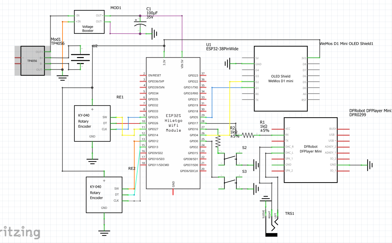
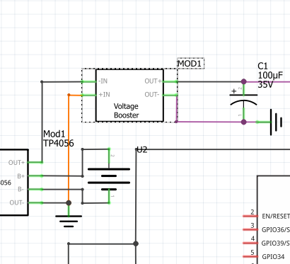
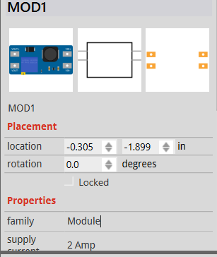
The topmost “rotary encoder” appears to be a voltage booster???
@vanepp can you help me work on his sketch (as of now:)
MP3_ESP32_ONLYSCHEM-v1.1.fzz (75.2 KB)

i wasn’t trying to trick you ![]()
![]() but the voltage booster is a voltage booster, i didnt use a rotary encoder as a replacement
but the voltage booster is a voltage booster, i didnt use a rotary encoder as a replacement ![]()
Then it might be my problem… Peter, can you help me look at it?
I;m currently looking at the schematic. There are a number of issues that I see, I’ll be back with some questions when I finish.
Peter
1 Like
im ready to answer those questions ![]()
![]()
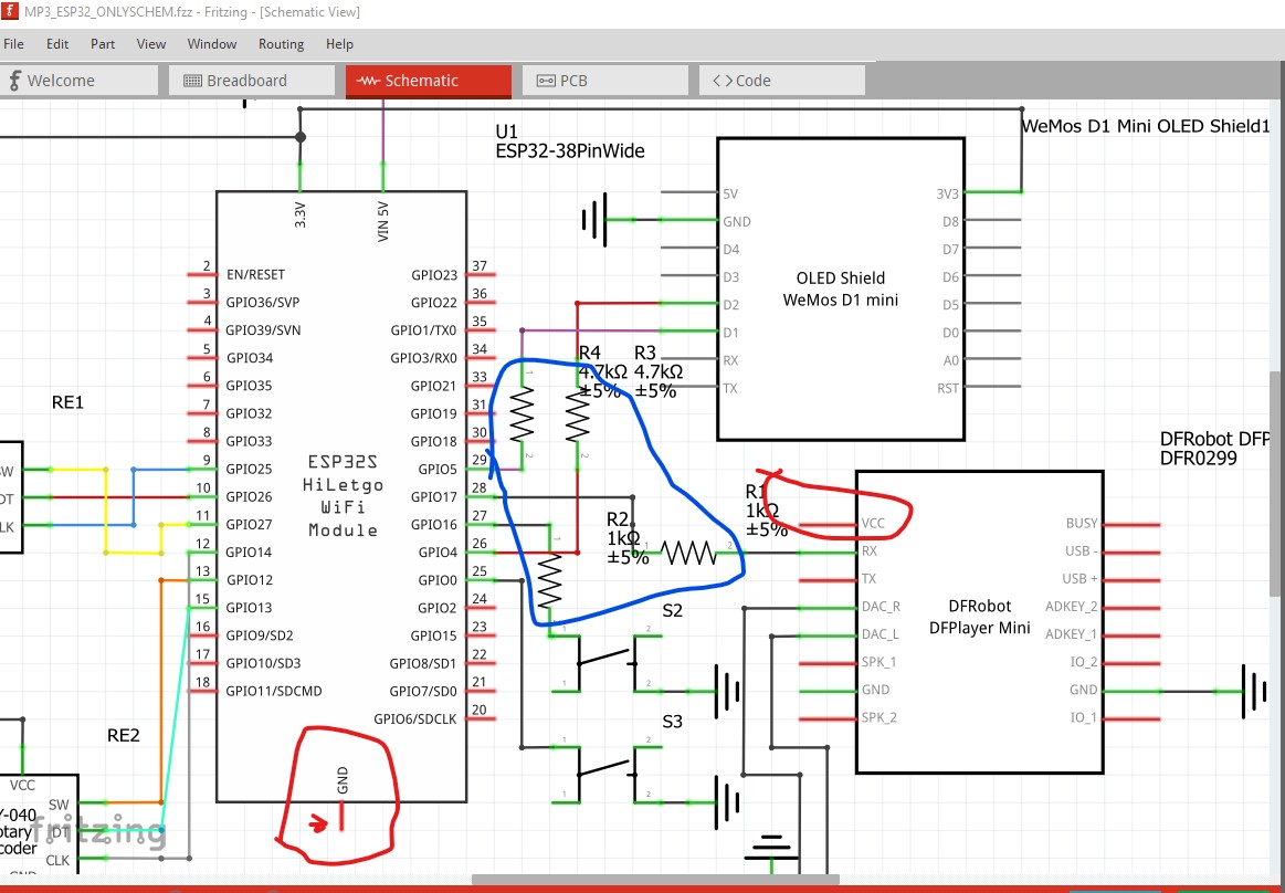
OK here are my first question/ comments. You are missing power connections to a couple of the boards. Without it they won’t run (circled in red.) It looks like they both need to be 3.3V which is good as that doesn’t need level translation. The ground on the CPU board is missing and the part is not correctly aligned to the grid (I will see if I have a corrected version of the part and correct it if not.) The resistors are a puzzle, why do you think you need them? As far as I can see they will only potentially reduce noise immunity by lowering the signal levels without providing any advantage but I may be missing something. I don’t know it the ESP32s have setable internal pull up resistors like the Arduino but it would be safer to add external pull up resistors to the two switches (again to increase noise immunity.)
The next is a cosmetic issue only, it will work as is and there may be a reason for doing it this way.
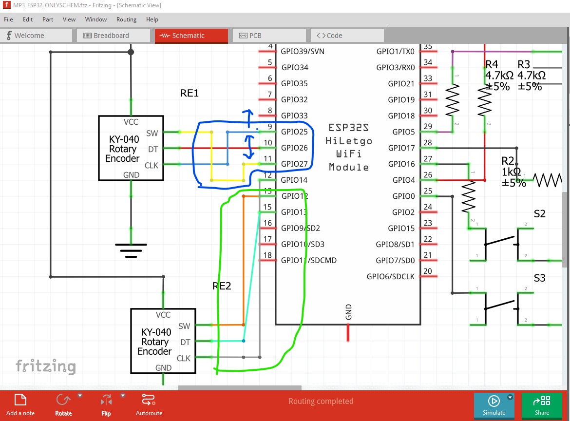
Inverting the IO pins (which would require a corresponding change in the ESP32 software) and moving the top one up one IO pin would improve schematic readability considerably. Similar change on the bottom encoder, change to order of the pins (with the associated software change) would make schematic much more readable. Is there a reason the pins need to stay as they are? I’m currently looking at the DFR MP3 palyer to see what VCC it wants (and if it will or does take 3.3V as if it is 5V you may need level translators as I think ESP32s are 3.3V and probably not 5V tolerant.
edit:
Looks like the MP3 player accepts 3.3V or 5v (it appears to be aimed at a 4.2V Lipo battery) so 3.3V would be appropriate here to the output levels (if used) are correct.
Peter
OK! Can you help me modify this file
MP3_ESP32_ONLYSCHEM-v1.1.fzz (75.2 KB)
I added pull-up resistors to make sure the I2C bus works properly by keeping the data lines HIGH when idle. (although i dont know if this specific model has internal pullups )
The VCC connection of the dfplayer was most probably a silly mistake made by me hehe when i was deleting wires to add the pull up resistors .
the connections from RE1 to the GPIO pins was merely cosmetic , and yeah for readability i might change the gpio pins.
and GND of the esp32 was also a silly mistake please forgive me ![]()
Pull up resistors need to be from the pin to (in this case) 3.3V not in the data path. OK, with this I’ll modify schematic to make all these changes. I am currently correcting my fixed version of the ESP32 part (mine has the 0.05in offset on the ground wire too) and will replace that both in the forum and in the sketch. I should have a modified schematic up in a bit for review and once the schematic is right then I can route pcb.
Peter
ahh , so i needed to keep it in parallel instead of series and connect it directly to 3.3v , got it , Thanks
Also thanks for reviewing the schematics and checking the esp32, i never wouldve noticed it
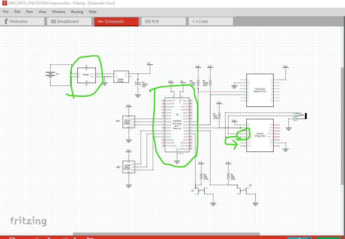
OK here is an updated sketch (so far schematic only)
MP3_ESP32_ONLYSCHEM-improved.fzz (88.4 KB)
Now to the changes. I swapped the tp4056 module (which is only a charging module) with one that also does BMS to prevent overloading the battery. It has a Fritzing part available which is in this sketch but here is a copy of the part
TP4056 Module.fzpz (30.3 KB)
where it is from
https://digitalconcepts.net.au/fritzing/index.php?op=parts
and documentation on what it does (basically limits the current output from the battery to prevent fires or explosions which is likely desirable as liPo batteries are dangerous!)
edit it would help if I included that link …
As well there is a new copy of the ESP board (the old one was badly formatted and took a lot of time to fix up) and another question: do you want the DAC outputs (which are intended to feed an amplifier) or the speaker outputs (which will drive up to 2 watts of power.) I would think you would want the speaker output going to the output jack if you want to use headphones but I don’t know for sure (and it affects the pcb routing.) As well I changed the IO ports around to simplify routing and added pull up resistors to the various IO ports and added power and ground to all parts. IF this suits I will route pcb to implement it.
Peter
Thanks , I just came home from swimming , ill take a look at this
Thank you for the improved TP4056 module , this is extremely suitable , and for DAC L & R I guess we can do that but we have to include a resistor and capacitor to prevent current spiking and reducing distortion , I think the only change being DAC now , its great!
Thank you for routing the PCB in advance
OK, on to the fun of laying out pcb. There are a few issues here.
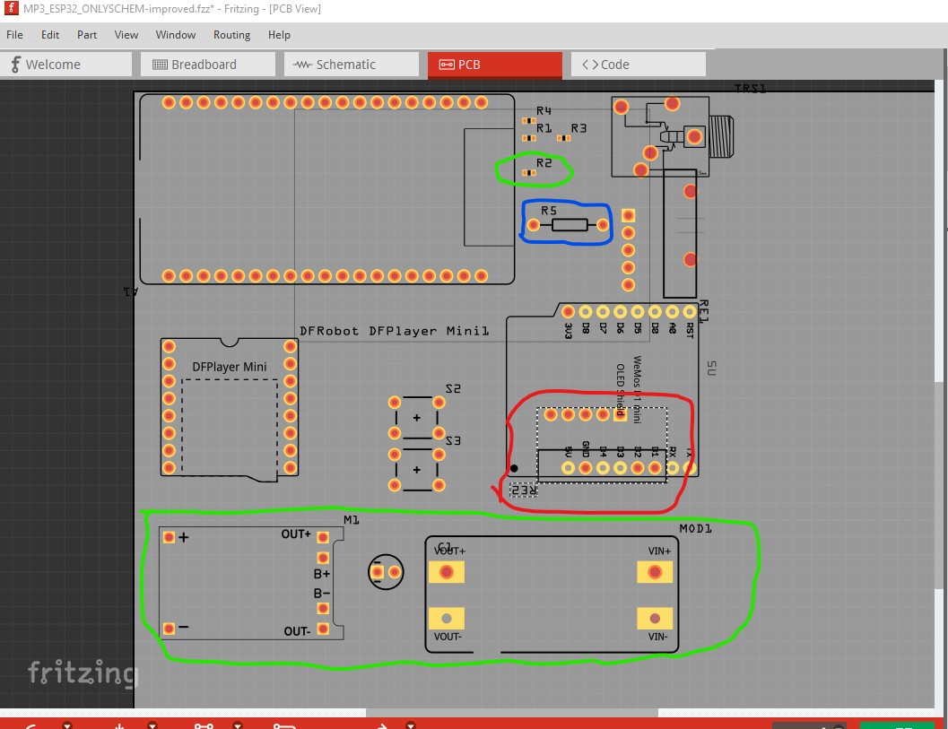
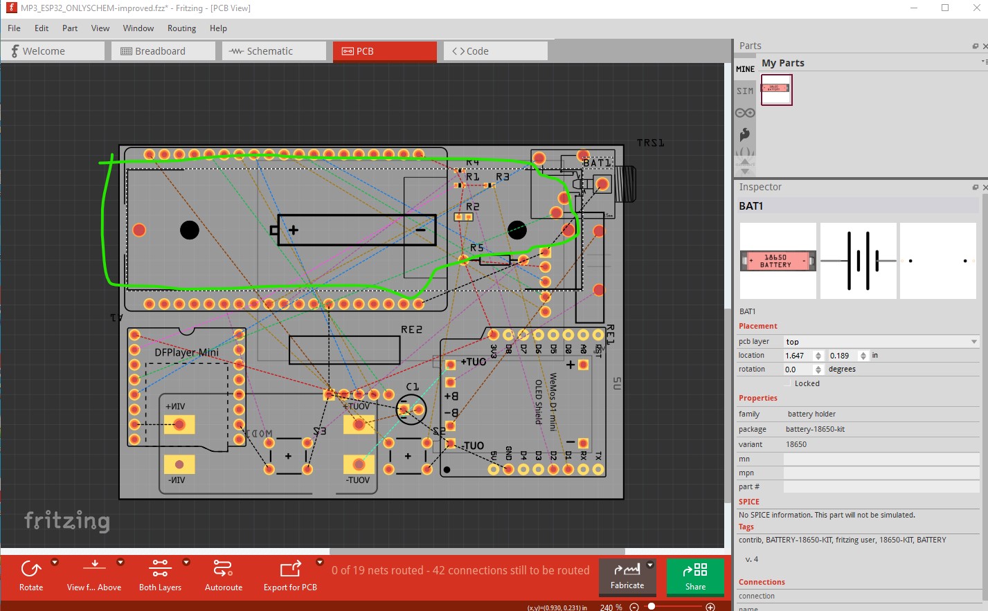
First item is type of resistors. You used 0402 SMD resistors, a better bet would be to use 0602 which are larger and the best bet would be use THT (all of which are shown in the image.) There is enough space that THT shouldn’t be a problem and they are much easier to install and solder than SMD.Here I started from your original sketch and placed the parts were they were in that, and then increased the size of the pcb to show the extra parts we have added and now need to find space for on the board. I assume there are size limits that you would like to achieve but that may not be possible. The rotary encoder re2 circled in red won’t fit there. It is overlapping with the Wemos OLED display both on the top of the board. It could be moved to the bottom of the board with the battery, but then the oled wouldn’t be visible nor could you access the switches from there. There is a similar issue with the charging module and the boost module. They can be put on the bottom of the board beside the battery. Doing that makes all the parts fit in the original size of board that you had like this (at least mostly, the battery overlaps with the converter slightly noted in red here.)

all the parts with green arrows are on the bottom of the board. The overlap could be cured by using a 18650 battery instead. There are Fritzing parts for both SMD and THT battery holders for 18650 batteries. This is the THT version of a single cell holder and probably your best bet. You would probably need to drill the mounting holes and screw it down to the board for mechanical strength while removing the battery from the holder and make sure that there is enough room under the ESP board to clear the screw heads
Tell me what you would like to do (or suggest something completely different if you have space constraints!) although it will likely be tomorrow before I answer at this point.
Peter
I agree with you on the THT resistor part since space isnt really that much of a constraint but id like to keep it sorta small and RE2 overlaps with the OLED display. Since both need to be accessible, I’ll move RE2 to the bottom side with a hole in the board for its shaft and the charger and booster modules are bulky so we can move them to the bottom and use vias to connect them to the top layer right? and for the 18605 we can mount it below the ESP and mount the esp in the case using headers. The OLED can stay in the top right , unless you suggest a better OLED screen which is better . Boss , this is upto you, youre the expert ![]()

also are these black holes for mounting?
if its likely tomorrow that means its nightime in your country , you should sleep and be well rested
The encoder on the bottom won’t work. To fit (because the pins are down) it needs to flip over so the shaft would point down not up. We would be better to move it. There are lots of OLED parts available if you aren’t tied to the Wemos one I’ll provide a list of the ones I know of and you can choose. I think some of them are likely smaller. The booster modules are already on the bottom as they overlap other components if they aren’t. You may be better with a 3.5mm jack that connects via wires (as that is easier to mount to the case) which would likely free up board space (but then we need to be careful to make sure it has space where it will go. Do you have the case you want to fit this in to already or are you going to 3d print a case? Knowing what the case size constraints are would likely be useful. A solder tab jack like this one
https://www.extron.com/product/aap135smjsc
(picked at random, there are lots of these) would free up board space as it will connect via a 3 pin header and wires. The OLED display can be done similarly if you like. There is a 4pin 1.54inch one, a 2.43in one (may be too big) , a 1.44in color one (you would need to check these to see if there are ESP libraries available though), a 1.3in 240x240 one, 0.96in 80x160 (8pin interface though), the last two generic ones (with different pin layouts) may be the closest to the Wemos ones as they are SPI. Again they can be mounted on the case and connect to a 4 pin header on the pcb via wires which gives you flexibility. Look them over and see what suits you. A search in the forum search bar or google for “fritzing part OLED display” (optionally with a size such as 0.96in) should turn up more as there are lots out there. Here are the ones above as .fzpz file, a search in the forum search bar should turn them up as they are all posted here.
oled-display-1_54in-4pin.fzpz
OLED-display-2.43in-SSD1309.fzpz
1_44in-color-tft-display.fzpz
lcd-1.3in-240-240-ips-st7789vw.fzpz
lcd-color-display-0.96in-80x160-8pin-interface.fzpz
OLED-128x64-I2C-Monochrome-Display-GND-VDD.fzpz
OLED-128x64-I2C-Monochrome-Display-VDD-GND.fzpz
Yes, although by default they are only on silkscreen and you need to drag a hole part in to the sketch to get the hole.
Peter
we can move the rotary encoder to another place and as for the wemos oled shield, if we replace that with the 1.54 inch it should save us space in theory and we dont need to have space for the OLED headers, and we would be better off with a solder tab like the one you sent , i dont have strict space constraints as ill make an acrylic case for it but a 5x3 inch case will be the maximum as i need it to be poratble , height i dont really think should be THAT much .
@vanepp can you please send the files of the OLED screens ? i cannot download them
I found multiple 1.54inch OLED screens like this waveshare one and they all seem to share the same design https://www.waveshare.com/1.54inch-oled-module.htm