halo , this is my first project using an ESP32 and and im making a portable mp3 player , so it has a 1100 mAh Li-Po battery , an ESP32 , DFPlayer Mini , OLED screen , 3.5mm jack and a few rotary encoders and switches . im open to any advice on how to improve my pcb .
NOTE:i only made the pcb and didnt bother to create breadboard and circuit diagram .
MP3_PLAYER_ESP32.fzz (72.4 KB)
i apologise if anyone has a heart attack looking at this ![]()
![]()
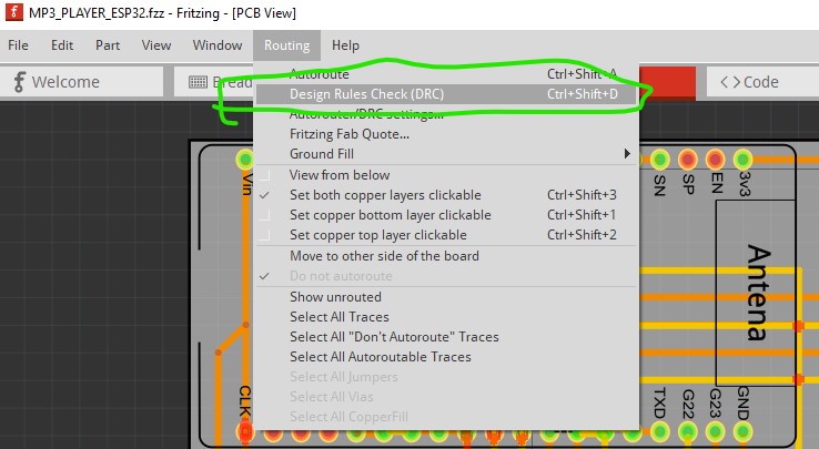
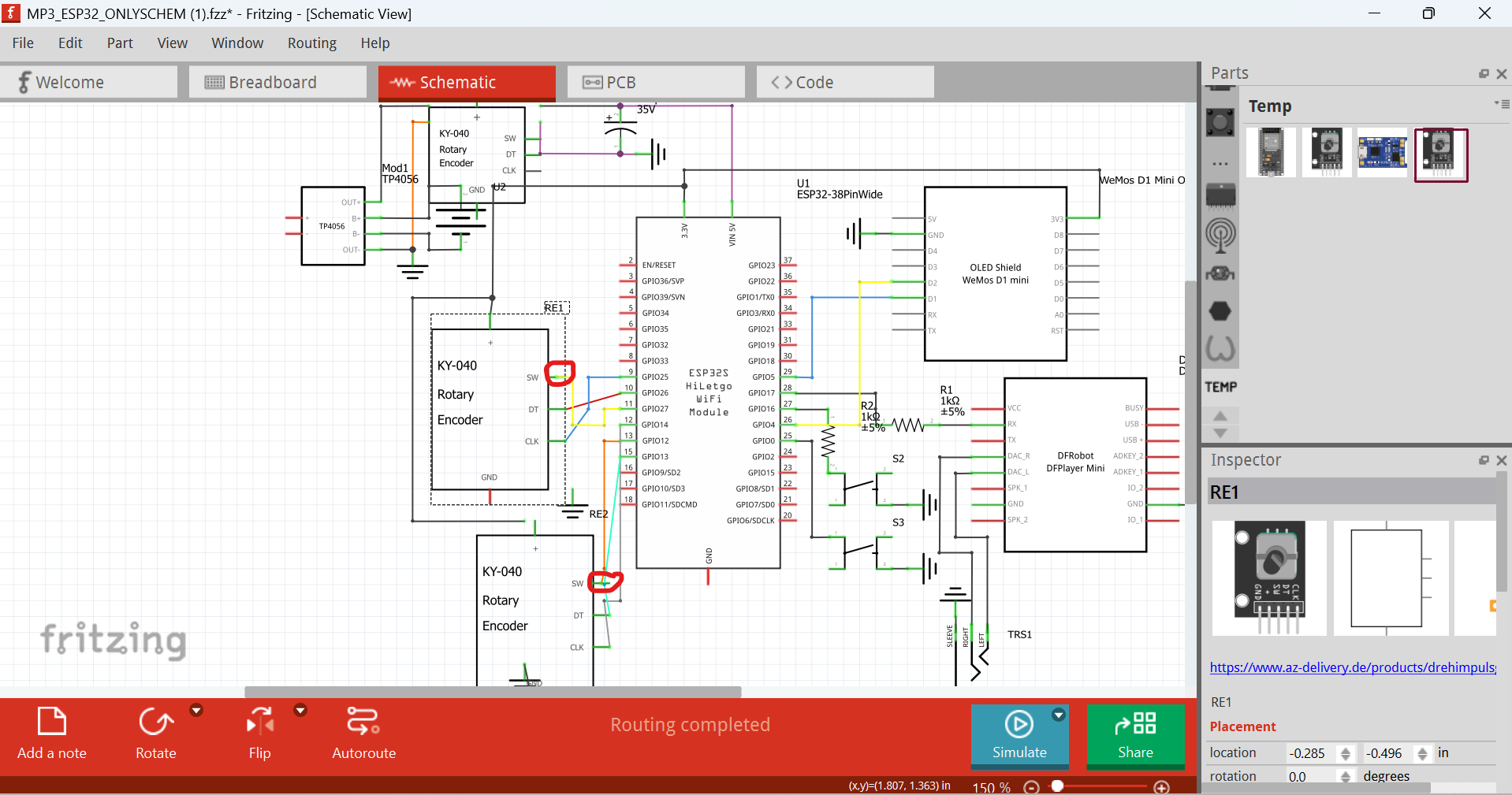
Well first thing to do is run DRC which rightly points out your pcb is entirely broken.
the various traces circled in red here that cross each other will and do cause shorts which will make this not work.
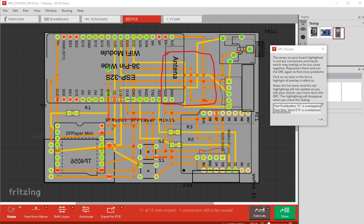
As well you need to finish the routing the message on the bottom indicates there is on unrouted path which is a short between ground and the G19 pin likely from either breadboard or schematic view. As well R1 is shorted by the trace running through it and is essentially non functional.
As well the trace on the left shorts Vin with the clk pin which is unlikely to be a good or desirable thing. The rotary encoder likely needs to move out from the wemos cpu board as it is unlikely to be able to connect there unless it is on the bottom of the board and the wemos is on the top and even then that isn’t a good idea.

The second thing to do is to route schematic as it will provide a check that things are connected the way you expect them to be. I would in fact start by correctly routing schematic (and likely breadboard to allow bread boarding this thing to verify it works before ordering boards!) Both of those can be done by routing schematic then using the rats nest lines to route connections in both breadboard and pcb.
Peter
1 Like
oh god ![]()
![]()
![]()
![]() , this is both sad and funny at the same time lol , thank you so much for telling me all the faults , ill def correct everything
, this is both sad and funny at the same time lol , thank you so much for telling me all the faults , ill def correct everything
But better than having ordered the boards and discovering your problems them (which has happened …)
Peter
ahh yes , definitely , thank youu
@vanepp can you help me fix the routing please? i cant fit all the wiring properly
Probably not. There isn’t enough information on what is supposed to connect to what. The shorts in pcb are reflecting in to schematic. I’d suggest starting in schematic and make the connections there that you want. With that done I can route pcb.
Peter
1 Like
okayy lemme make it , ill make the schematics
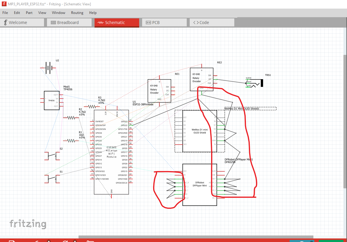
here you go the new schematics diagram , it took me sm time cus my mom made me sleep last night lol, sorry for the delay
MP3_ESP32_ONLYSCHEM.fzz (72.8 KB)

oh shi i forgot the resistors wait
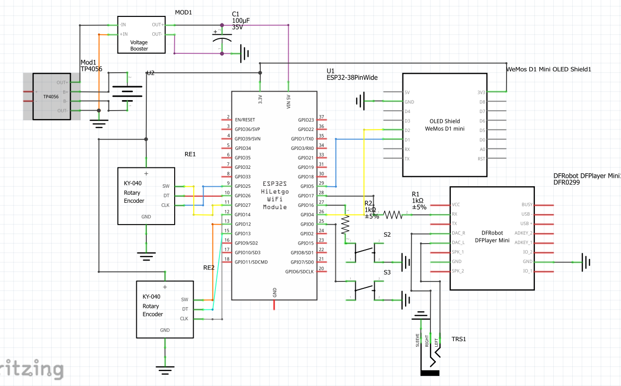
heres the updated schematics
MP3_ESP32_ONLYSCHEM.fzz (73.8 KB)
Thanks I’ll have a look at it
1 Like
do you think i should use pull-up resistors between the oled sda and scl to esp32?
Yes sleeping is good (sorry to agree with your mom ![]() , tiredness produces errors …) Please upload the sketch (the .fzz file, upload is 7th icon from the left in the replay menu.) While I could recreate the schematic from an image the .fzz file is better as I can’t introduce an error by missing something.
, tiredness produces errors …) Please upload the sketch (the .fzz file, upload is 7th icon from the left in the replay menu.) While I could recreate the schematic from an image the .fzz file is better as I can’t introduce an error by missing something.
Peter
Yah he just uploaded the file2 posts back
It might have come from here
Oh another thing – parts by DFR aren’t good. I’ll see if I can fix them
Yes it looks like I made but never published an improved version of that part. You will likely need to do a delete minus (which deletes the part, but saves the traces) of the part, then delete the current part from the mine parts bin, then shutdown Fritzing answering yes to save parts and save parts bin (to really delete the part.) Then restart Fritzing load this new part and drag the wires to connect them correctly.
KY-040_AZ_Rotary_encoder_v0-improved.fzpz (9.0 KB)
Peter
haha yep , i downloaded the part from there , ill download the part created by @vanepp and follow his instructions