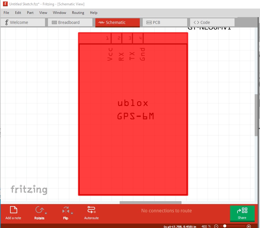
there are no connections defined in schematic thus the red rectangle. The pads in pcb should be circles not paths and are too large (the holes should be 0.038in for 0.1in headers not 0.067in
; NON-PLATED HOLES START AT T1
; THROUGH (PLATED) HOLES START AT T100
M48
INCH
T100C0.066941
%
T100
X018116Y017765
X017092Y017777
X016134Y017763
X015111Y017777
T00
M30
the schematic layerId has a capital S (Schematic rather than schematic) and thus doesn’t match the fzp file and won’t export as an image. There are bus definitions that don’t have pins in the fzp file as well. These two tutorials (which apply to current Fritzing versions) may help: