The HC-SR04 part has a second image that is a top view. I thought I might be able to use the parts editor to modify it to add a fifth pin and change the layout slightly to accommodate it. I did a search for a tutorial on how I might do this but I am completely baffled. So far, what I have found is that the tutorials haven’t been updated for the latest release of the editor so I’m at a loss how to do what I want. Can you give me any guidance? If there are any current tutorials that you can point me to, I’d like to try to learn how to do this myself.
These two tutorials apply to the current Fritzing versions (although successful part creation is not easy.)
I lately learned there aren’t links to the videos in Old_Grey’s tutorial so you need to do a google search for the title and then they come up on YouTube.
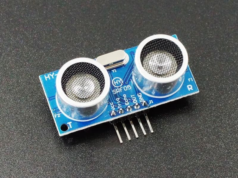
Is there something wrong with the HY-SRF05 part listed above?
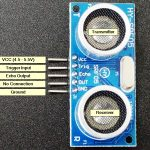
There isn’t anything wrong with the part you found (thank you again) but I’m teaching an introduction to electronics class for some 12-14 year old students and they have problems with abstractions. I’m making a Fritzing document with the details on how to connect the part to an Arduino to put in a PowerPoint presentation for them so they can see the connections visually. They will be plugging the sensor into a breadboard and so I need an accurate top view of the part to show the proper connections.
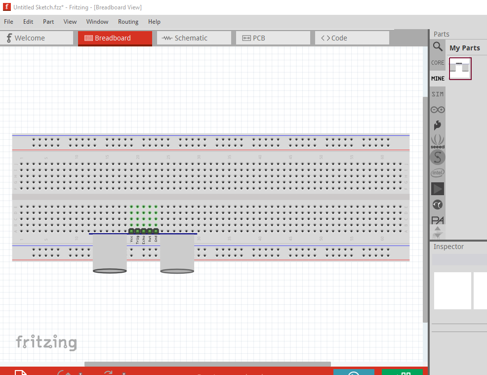
I was trying to modify the existing HC-SR04 Variant 2 but I’m finding the process difficult. I found a Sparkfun tutorial at Make Your Own Fritzing Parts - SparkFun Learn but I’m still confused.
It looks like I will need to learn Inkscape as well. Is that an accurate assumption?
Yes (or another svg editor, but Inkscape has the most control of any I know.) I’d advise using FrtizingCheckPart.py (pointer in my tutorial) as all the svg editors do things that Fritzing doesn’t like (such as add px to the font size for CSS compatibility) which tends to cause problems by changing the font size to too large or too small. As far as I can see the main difference between the two is the right angle connectors on the SR04 part (and the extra connector which means you need to modify all three views to add the extra pin!) It is easy enough for me to add them to the SR05 part if you like.
I don’t have any objection to you learning to make parts, but as noted it is complex and takes a long time to learn (especially if you aren’t familiar with an svg editor) and tends to bite without warning (usually by the new part malfunctioning.) although FritzingCheckPart.py tends to sort of help there (you need to be able to read the xml to figure out what it is telling you though!) I tend to fix and make parts for folks for that reason.
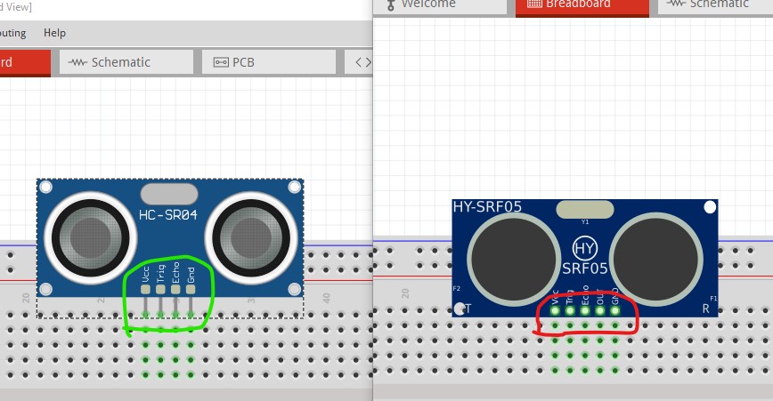
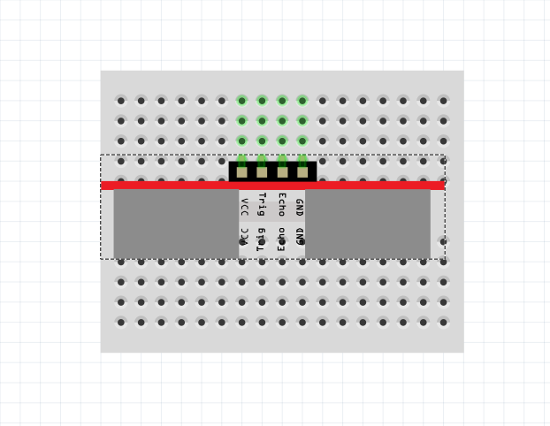
This is what I’m trying to achieve, although with 5 pins instead of 4. The wires will plug into the breadboard behind the sensor so showing the front view would be wrong because the wiring would be backwards. The experiment involves coding an Arduino to read distance and the breadboard will hold the sensor steady to give better results.
The important thing for my students is to be able to see which wire goes where when hooking things up.
Having reached the age of 72, I’m not sure I have enough years left to devote to learning Fritzing part creation. As long as you are willing to help, I’ll be happy to accept.